
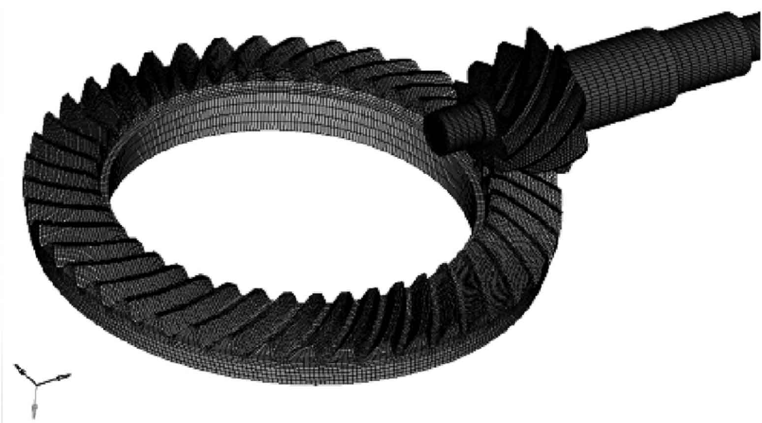
The established three-dimensional model of hypoid gear is saved in *. STP format and imported into the software HyperMesh for mesh generation. In order to improve the calculation accuracy of hypoid gear meshing process and reduce the influence of hypoid gear geometric simplification on gear meshing, this paper establishes a finite element model of the whole hypoid gear and selects hexahedral mesh, The number of corresponding elements is 276722 and the number of nodes is 237804. Finally, the finite element mesh of this hypoid gear is obtained, as shown in Figure 1.
The advanced finite element analysis software ABAQUS has unique advantages in solving nonlinear models such as hypoid gear meshing. In this paper, standard / static and general solvers are selected for quasi-static finite element analysis of hypoid gear meshing process. Taking the meshing process of hypoid gear of drive axle under constant speed driving condition as the research object, the input speed of pinion and the output resistance torque of large gear are determined according to the driving condition.
The following points should be paid attention to in the establishment of finite element solution model of hypoid gear: the definition of hypoid gear material, and the linear reduced integral element c3d8r with hourglass and self-locking control is selected for hexahedral mesh. In order to ensure the convergence of the solution process, two analysis steps are defined: ① load loading, set the time length to 1, turn on geometric nonlinearity, and other parameter values are the default values; ② For meshing and rotation of hypoid gear, the time length is set according to the rotation speed of hypoid gear and the rotation angle of gear, and the geometric nonlinearity is also turned on. Other parameters are the same as those in the previous analysis step. Surface to surface contact tooth pairs are established between large and small gears with quasi double curved surfaces. In the contact attributes, the tangential behavior friction coefficient is 0.1, the normal behavior is’ hard ‘contact, and other parameters are set by default. In the load loading analysis step, fix the input end of the pinion, restrict all degrees of freedom except rotation around its own axis on the output end of the pinion, and linearly load the driving resistance torque at the output end with a slope. In the step of meshing and rotation analysis of hypoid gear, all degrees of freedom at the end of hypoid large and small gear except around its own axis are constrained, the input angular displacement of pinion is also linearly loaded on the slope, and the loading of large gear is the same as the transient resistance moment in the previous step. In order to increase the stability of the meshing process, the initial speed of the active and passive gears is defined in the initial conditions. In the boundary condition module, the initial meshing speed of the hypoid gear is defined by using the ‘predefined field’.


Here, first simulate the vehicle running at a constant speed of 40 km / h, input the speed of 9.6 rad / s at the input end of the pinion and 9 500 N · m resistance torque at the output end of the large tooth. As shown in Figure 2, the maximum principal stress corresponding to the large and small hypoid gears can be obtained. It can be seen that there is a large compressive stress at the tooth surface due to contact extrusion, and the contact part is approximately elliptical, Large tensile stress appears at the tooth part due to tension. At this time, three teeth of the hypoid gear are engaged, the maximum compressive stress appears on the tooth surface of the hypoid gear at the middle part, and the maximum tensile stress appears at the corresponding tooth root. It can be seen from the finite element analysis results that the contact of the gear always transits from one end to the other end in the process of quasi double curved surface meshing, Therefore, there will be no sudden change in meshing stiffness like spur gears.