
At present, most of the spiral bevel gears used in China adopt the American Gleason gear system, and its design and manufacturing methods are closely linked. The theory of spiral bevel gears established by the general Gleason technology is more complex. Therefore, it is necessary to find other methods to achieve the same effect and make its theory more simple and clear. A unified machining coordinate system of left and right rotating gears is established, and the machining process of spiral bevel gears is simulated by computer.
A unified machining coordinate system of left and right rotation is established, which is helpful to simplify the machining and calculation of spiral bevel gear. According to the structure of Gleason gear milling machine currently applied, the establishment is shown in Figure 1:

Z0 is perpendicular to the shaking table through the center of the shaking table and points to the outside of the shaking table. O0 is the center of the machine tool, x0-y0 plane is the plane of the machine tool, and {o0, x0, Y0, Z0} is the static coordinate system{ O1, x1, Y1 and Z1} are the coordinate system in which the origin rotates with the shaking table at the center of the tool rotating body, that is, it is stationary relative to the shaking table{ O2, X2, Y2 and Z2} are the coordinate system established on the tool rotating body, Z1 and Y1 are in the same direction and point to the outside of the shaking table{ O3, X3, Y3 and Z3} are coordinate systems fixedly connected to the tool tilt body, and Z3 is the axis direction of the tool tilt body{ O4, x4, Y4 and Z4} are coordinate systems fixedly connected with the cutter head, and Z4 is the direction of the cutter head axis, in the same direction as Z3.
The following tool transformation matrix can be obtained:
During matrix transformation:
Q – shaking table angle
J – Installation rotation angle during tool rotary machining
I – inclination angle of rotary tool axis
θ— Cutter head angle
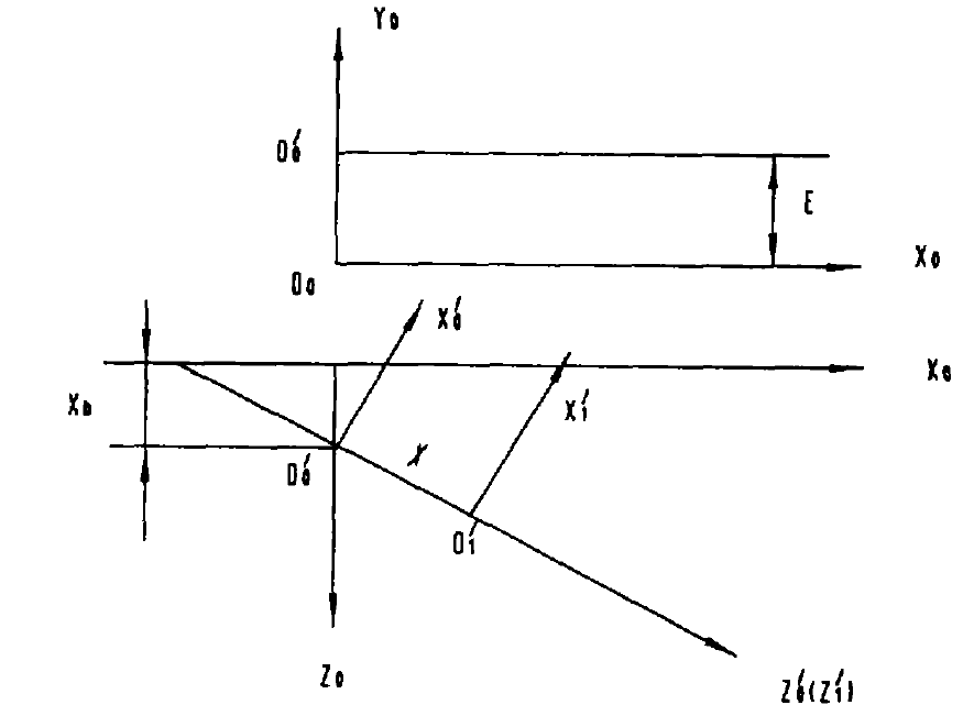
For the workpiece, the establishment of the workpiece coordinate system is shown in Figure 2. The coordinate system {o’0, X’0, y’0, Z’0} can be regarded as translating (0, e, XB) first by {o0, x0, Y0, Z0}, and then rotating (90 °) around the Y0 axis- δ) And get it{ O’1, X’1, y’1, Z’1} are the coordinate system established on the workpiece, Z’1 is the axis from the small end to the large end, and the origin o’1 is selected at the blank calculation point.
Thus, the following workpiece transformation matrix can be obtained:
Where:
δ— Installation angle;
ψ— Wheel blank angle;
E – vertical wheel position;
X – axial wheel position;
Xb – bed