
In the current automotive hypoid gear processing methods, generally, when the large wheel cone angle is large, the forming method (HFT) or the generating method (HGT) can be used. When the large wheel cone angle is small, the generating method must be used, and the small wheel can be processed by the generating method. The most widely used modeling method of hypoid gear tooth surface is the conjugate surface method proposed by Litvin. Litvin studies the production process of hypoid gear, obtains the points on the hypoid gear surface through spatial transformation of the points generated by tool rotation during gear machining, and interpolates the discrete data points on the hypoid gear surface, High precision tooth surface can be generated. Medium u, θ Is the tooth surface parameter formed by tool rotation, ψ Is the rotation angle of tooth germ. The modeling process is described as follows: firstly, the tool coordinate vector is obtained according to the tool parameters, and then the coordinate transformation of the above vector is carried out to obtain the surface formed by the tool. Then, the tool surface is transformed into the hypoid gear coordinate system according to the machine tool parameters, and the meshing equation is obtained according to the hypoid gear meshing principle. Then, according to the fact that the point on the gear tooth surface must be on the gear tooth embryo, Finally, these discrete points are reconstructed by non-uniform B-spline curve (NURBS), and the three-dimensional digital model of hypoid large and small gears is obtained.
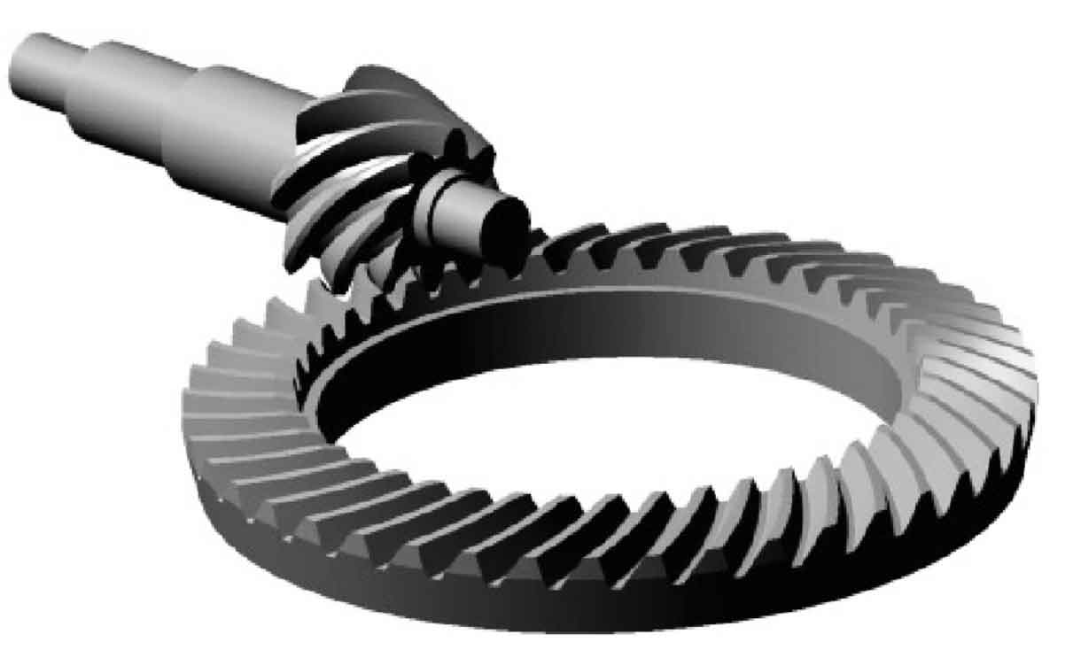
The HFT hypoid gear is analyzed, that is, the pinion is processed by the generation method, the large gear is processed by the forming method, the tooth germ parameters and machine tool processing parameters of the hypoid gear, and finally the three-dimensional CATIA model of the hypoid gear is obtained, as shown in the figure.
Establishing a three-dimensional (3D) geometric model of a hypoid gear involves several complex steps, as hypoid gears have unique geometric features compared to other gear types. These gears are characterized by their hyperboloid shape, which allows the axis of the gear to be offset from the axis of the pinion. This design is crucial for applications requiring compact arrangements and efficient power transmission at varied angles. The modeling process typically involves the following stages:
1. Gear Geometry Definition
- Gear and Pinion Parameters: Start by defining the basic parameters of the hypoid gear set, including the number of teeth, module, pressure angle, helix angle, and the offset distance. These parameters are essential for determining the overall geometry of the gear and pinion.
- Tooth Surface Equations: Develop the mathematical equations describing the tooth surfaces of the gear and pinion. For hypoid gears, the tooth surfaces are generally defined by a combination of involute and spiral functions, modified to account for the gear offset.
2. Gear Tooth Generation
- Base Surface Generation: Utilize the defined gear parameters to generate the base surfaces of the gear and pinion. This involves calculating the shapes of the gear bodies before the teeth are cut into them.
- Tooth Profile Cutting: Apply the tooth surface equations to the base surfaces to model the actual tooth profiles. This step requires precise calculations to ensure that the tooth profiles are accurately modeled for proper meshing and power transmission.
3. 3D Modeling Software
- Software Selection: Choose appropriate 3D CAD (Computer-Aided Design) software that can handle the complex geometries involved in hypoid gear design, such as SolidWorks, Autodesk Inventor, or specialized gear design software.
- Modeling Process: Using the CAD software, input the base parameters and equations for the hypoid gears. The software should be able to generate the 3D model of the gear set based on these inputs. Advanced CAD packages may offer specialized tools or plugins specifically designed for gear design, facilitating the modeling of complex gear types like hypoid gears.
4. Simulation and Analysis
- Meshing Simulation: Once the 3D model is complete, simulate the meshing of the gear and pinion to verify that they interact as intended. This step is crucial for identifying any potential issues with the gear design, such as interference or improper contact patterns.
- Stress and Strain Analysis: Perform finite element analysis (FEA) on the model to evaluate the stresses and strains experienced by the gear teeth during operation. This analysis helps in optimizing the gear design for durability and performance.
5. Iteration and Optimization
- Design Iteration: Based on the simulation and analysis results, make necessary adjustments to the gear parameters and tooth profiles. This iterative process is essential for refining the gear design to meet specific performance and manufacturing requirements.
- Optimization: Finally, optimize the 3D model for manufacturing, considering factors such as material selection, manufacturing tolerances, and surface finish. This step ensures that the gear can be produced efficiently and will perform reliably in its intended application.
Establishing a 3D geometric model of a hypoid gear is a complex and iterative process that requires a deep understanding of gear mechanics, advanced mathematical modeling, and proficiency in 3D CAD software. This process allows engineers to design, analyze, and optimize hypoid gears for a wide range of applications, ensuring efficient power transmission and performance.