The modeling module of ABAQUS software can effectively establish three-dimensional models, but most of them are suitable for three-dimensional model modeling with simple structure. For more complex models, the direct use of ABAQUS software modeling method will deepen the complexity of modeling. Therefore, SolidWorks software is used for three-dimensional modeling, and the gear model established by SolidWorks three-dimensional software is imported into ABAQUS finite element software for data analysis and solution by using the interface with Solidworks software contained in ABAQUS software.
1) Gear finite element modeling
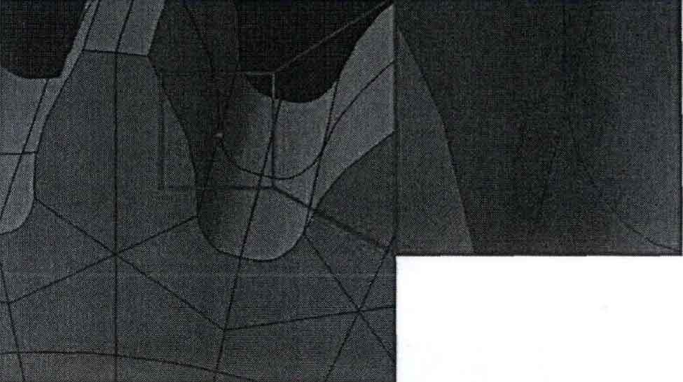
The variation law of stress intensity factor at the leading edge of pinion root crack is analyzed and studied. The research object is low-speed and heavy-duty gear. The three-dimensional model of two meshing gears is assembled by SolidWorks three-dimensional software. The seven tooth three-dimensional assembly model of the intercepted gear is simulated to simplify the calculation process. The cut model is imported into ABAQUS finite element analysis software, and the semi elliptical crack assembled to the tooth root of the gear is established in ABAQUS software. The location of the semi elliptical crack is shown in Figure 1.
2) Mesh generation and definition of fatigue crack
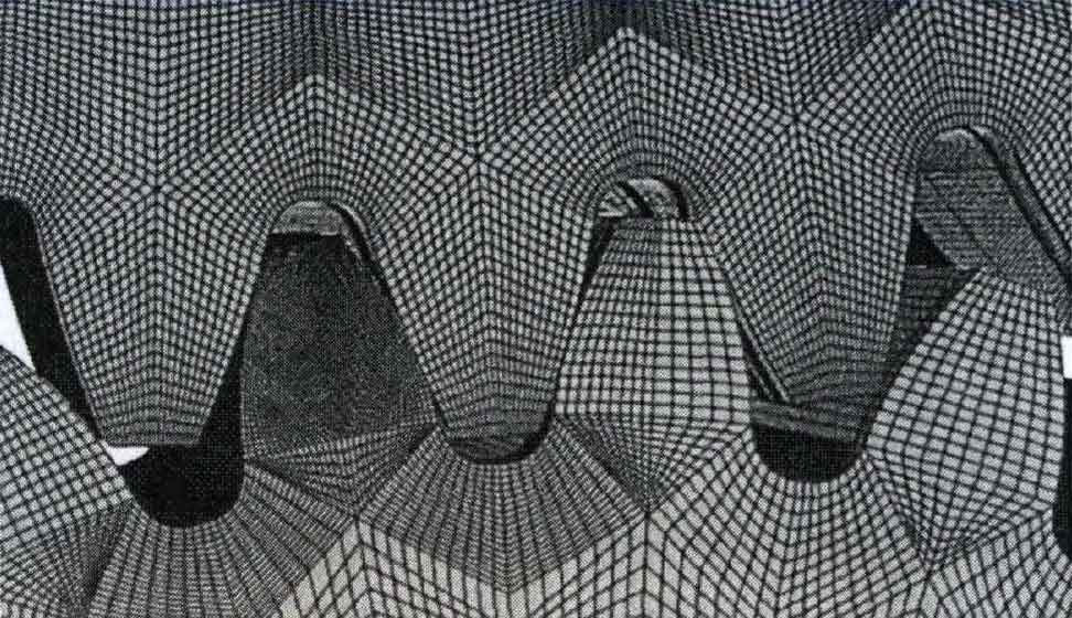
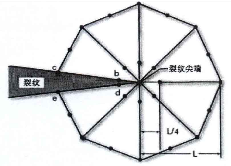
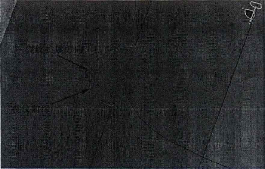
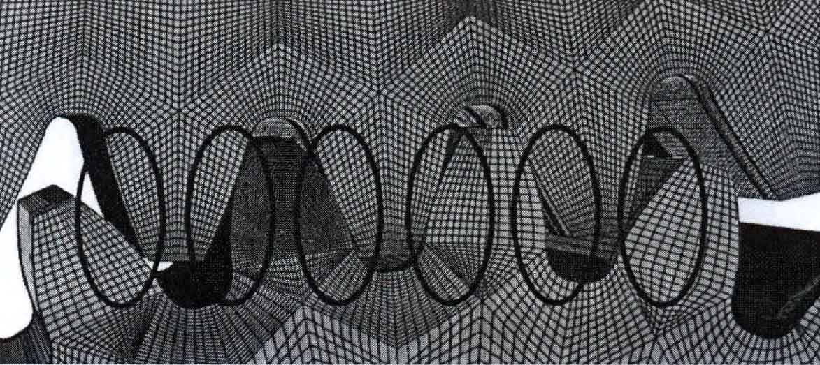
The meshing of gear is based on structure division technology. The mesh of the pinion is set as: except that the mesh size of the crack is 2mm, other meshes are uniformly set as 4mm. The grid setting of the large gear is: the grid is uniformly set to 6mm, c3d8r is selected as the unit type, and 760000 grids are divided in the gear. The division results are shown in Figure 2. In defining the mesh type, a 6-node triangular element mesh is set and applied at the crack tip. Change the position of the crack node at the tip and transfer it from the middle position to the quarter position, as shown in Fig. 3. This is determined by the singularity of the crack tip. For the definition of fatigue crack, the contour integration method is adopted. The minor axis direction is the semi elliptical crack propagation direction, and the center of the crack points to the endpoint of the minor axis, as shown in Fig. 4.
3) Application of boundary conditions
Set the boundary conditions, that is, the meshing part of the gear is set as face-to-face contact, as shown in Figure 5, in which 6 contact pairs of face-to-face and face contact. Set the gear material as: set 42CrMo as the material of big gear and pinion, set the property of the material and set the property as isotropy.
The boundary condition setting of gear pair mainly sets the boundary conditions of driving wheel and driven wheel. Setting of driving wheel: only the freedom of axial rotation, plus 200N * m torque. Driven wheel boundary condition setting: set the driven wheel as a fully fixed constraint. In the analysis step, the general static analysis step is selected. For the interaction area at the front of the crack, the contour integral method is selected to define it, and the initial increment is 0.1. The division rule is based on the rotation angle of the driving wheel. 1 ° corresponds to one division, in which the driving wheel rotates a total of 20 °. Assign a value of 0.15 to 6 the friction coefficient of the contact surface of the gear.

