
Example analysis of noncircular gear: the equation of transmission ratio i12 to be realized is as follows:
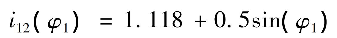
Where, the transmission ratio function is based on the rotation angle of the driving wheel φ 1 is the function of independent variable. In this paper, it is assumed that the module m of driving wheel is 2.5 mm and the number of teeth Z is 19. Because many factors need to be considered in the process of noncircular gear design, such as whether to undercut, whether the pitch curve is closed and convexity and concavity test, the process diagram of noncircular gear design is given in order to more clearly express the process of solving noncircular gear in this paper.
The following is to solve the noncircular gear according to the flow chart. First, determine the center distance of the driving and driven wheels, and calculate the installation center distance of the driving and driven wheels according to the formula:
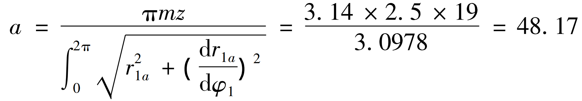
Therefore, the installation center distance of the main and driven gears can be calculated as a = 48.17mm. Because the center distance of noncircular gear has been calculated, the arc length of driving gear pitch curve can be calculated by simultaneous formula, which can be obtained by arc integral formula:
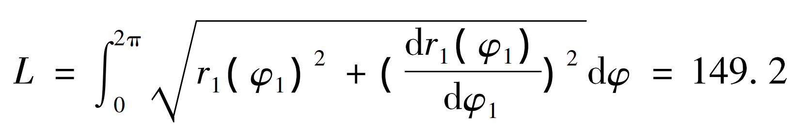
Therefore, it can be obtained that the arc length of the driving gear is 149.2 mm.
1.Undercut verification
Because the curvature radius of noncircular gear pitch curve changes, undercutting may be caused in the processing process, so it is necessary to verify whether undercutting does not occur. If undercutting does not occur, it is:
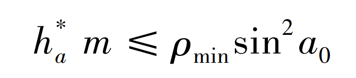
Where, ρ Min is the minimum radius of curvature of the pitch curve; A0 is the tooth profile angle of rack cutter, taking A0 = 20 °; Ha is the addendum height coefficient of rack cutter, which is defined as h * a = 1.
2.Sealing inspection
The position of the driven wheel is checked according to the following formula:
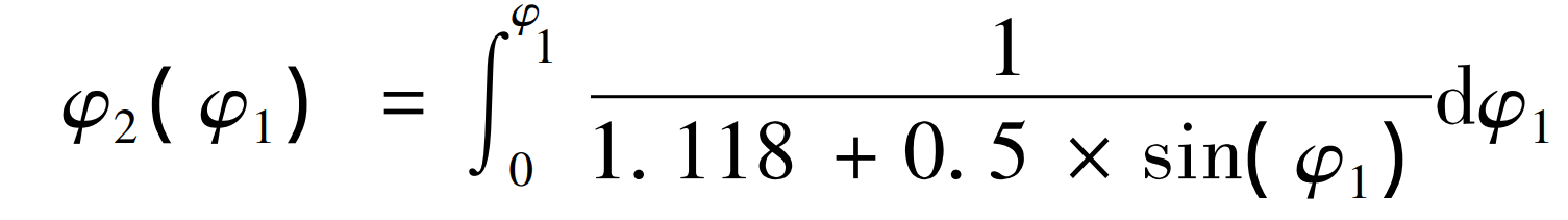
Calculate the function when φ When 1 = 2 π, φ 2 (2 π) = 2 π, that is, the driving wheel rotates for one circle and the driven wheel rotates for one circle, which meets the requirements of node curve closure.
3.Concavity and convexity inspection
Before machining noncircular gears, the concavity and convexity of the pitch curve must be known in advance, so the concavity and convexity calculation is carried out with reference to the literature.
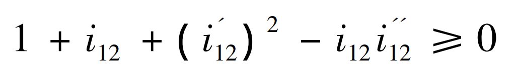
The conditions under which the driving wheel pitch curve does not appear concave are:

The conditions under which the driven wheel pitch curve does not appear concave are as follows:
After inspection, the pitch curves of the driving and driven wheels are convex.
4.Pitch curve of driving and driven gears
Given the transmission ratio function of the formula, the joint formula can deduce that the driving gear pitch curve is:

According to the formula, the pitch curve of driven gear can be solved as follows:
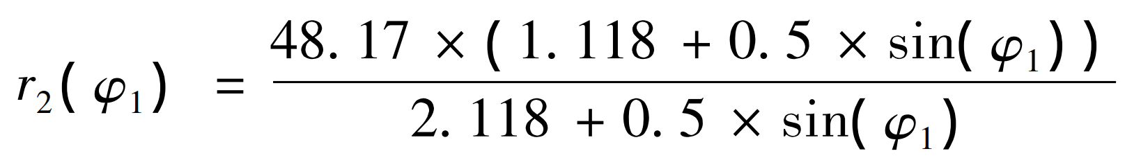
According to the calculation results of the formula, and then according to the center distance calculated by the formula, the pitch curve of the driving and driven wheels can be obtained by using MATLAB.
5.Rotation center of noncircular gear
Next, find the rotation center (focus) of noncircular gear. At present, the research on the rotation center of noncircular gear by domestic and foreign scholars is generally about elliptical gear. At present, the research on the rotation center of other types of noncircular gear is rarely introduced. This paper solves the rotation center of noncircular gear according to the relevant conclusions of elliptical gear. According to the pitch curve and center distance of the driving and driven wheels, the meshing position of the noncircular gear can be obtained, as shown in the figure. Next, find the rotation center of the driving wheel. The data of the driven wheel can refer to the calculation process of the driving wheel.

Draw the pitch curve of the driving wheel according to the formula, and the “long axis” of the noncircular gear can be calculated to be 48.17 mm, as shown by the thick line of the driving wheel in the figure, and the “short axis” is 46.82 mm, as shown by the blue line. Finally, the “focal length” can be obtained to be 5.67 mm, as shown in o1-c1 in the figure, C1 is the rotation center of the driving wheel during meshing transmission. Similarly, the focal length o2-c2 of the driven wheel can be obtained, and the rotation center of the driven wheel is C2. Next, the correctness of the rotation center of the noncircular gear wheel is verified. Take the tangent point of the driving and driven wheels as the initial point, find 6 points on the driving and driven wheels according to the arc length of the same length, and simulate the pure rolling motion of the noncircular gear. The center distance of the noncircular gear is the sum of c1-1 and C2-1, C1-2 and C2-2 respectively, and so on. The solution shows that the sum of the six data points is very close to the center distance of 48 17 mm, which proves that the rotation center calculated in this section is correct.