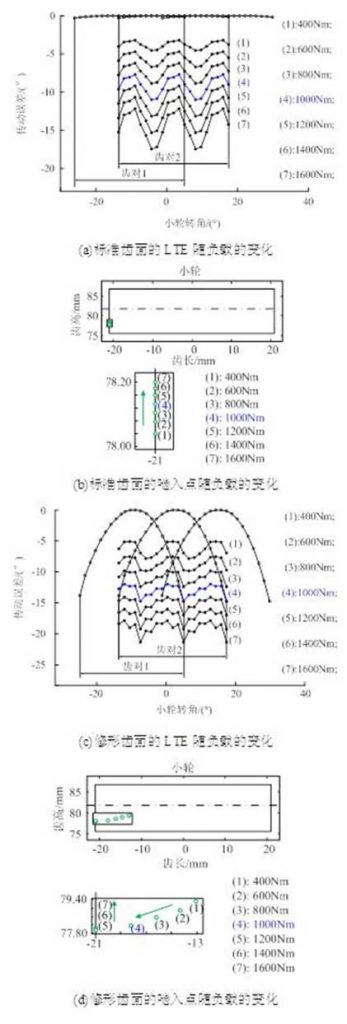
Figure 1 shows the calculation results of the load-dependent position of the rodent points on the standard and modified tooth surfaces.To calculate the position of the rodent point, TE and LTE are needed first, and then the position of the rodent point is obtained.
Figure 1(a) shows the change of LTE of standard tooth surfaces with load.The larger the load, the more deformed the teeth become, and consequently, the LTE becomes larger and larger.Figure 1(b) shows how the position of the standard tooth-side contact point varies with load on the small gear-side.It can be seen from the diagram that as the load increases, the rodent point moves from the root of the tooth to the web area along the edge.This is because as the load increases, the load deformation of the teeth increases, the pitch difference between the large and small teeth increases gradually, and the corresponding meshing interference advances gradually as the load increases.Therefore, as the load increases, the rod point moves from the root to the web along the edge of the pinion teeth.

Figure 1(c) shows the change of LTE with load on the modified tooth surface.Figure 1(d) shows the position of the screw-in point on the small gear tooth surface as a function of the load after tooth surface modification.After tooth surface modification, the actual overlap degree of the gear pair decreases. When the load is small, the contact area is only on part of the tooth surface. In the initial stage, the actual overlap degree of the gear pair increases with the increase of load. The clearance between the latter teeth is sufficient to compensate the effect of the previous teeth on the load deformation of (tooth on 1). When large and small gear teeth enter into mesh, they contact with the tooth surface, and the rodent point is from the tooth web.The area moves to the side of the teeth along the area.
When the load increases to a certain extent, the contact area between the large and small tooth surfaces will extend to the full tooth surface.At this time, the actual overlap degree of the gear pair is equal to the design overlap degree, and the gap between the teeth of the second tooth pair (tooth pair 2) is not enough to compensate for the effect of the previous tooth on the load deformation of (tooth pair 1). When large and small gear teeth enter into mesh, they contact the tip point of the large gear teeth and the edge of the minor gear modified tooth surface, which results in meshing interference.When the load is further increased, the actual overlap degree of the gear pair remains unchanged, equal to the design overlap degree. When entering mesh, it contacts the tip of the large gear tooth and the edge of the modified tooth surface of the small gear. As the meshing interference advances gradually with the load, the position of the meshing point will move from the root to the web area along the edge of the small gear teeth.

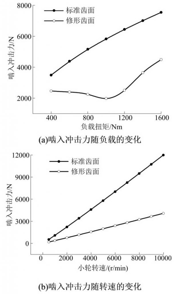
In Figure 2, the calculation results of the impact force on rodent with load and speed are given.Figure 2(a) shows the calculation results for the impact force of rodent in the load range from 400 Nm to 1600 Nm.On the whole trend, the impact force on the modified tooth surface was effectively reduced after tooth surface modification. At 400Nm, 1000Nm and 1600Nm, the impact force on the modified tooth surface was reduced by 29%, 66% and 40% respectively.It can also be seen that the impact force of the standard tooth surface increases with increasing load.In conjunction with the calculation results in Figure 1(b), it can be found that as the load increases, the position of the standard meshing point on the tooth surface moves along the side edge of the small gear tooth from the root to the web of the tooth, and the relative normal speed and meshing rigidity of the two meshing teeth at the meshing point increase with the increase of the load, so the meshing impact increases with the increase of the load.Unlike the standard tooth surface, the impact on the modified tooth surface decreases at the initial stage as the load increases, and is the smallest when the load increases to 1000Nm, and increases when the load increases further.
In combination with the calculation results in Figure 1(d), it can be found that in the initial stage, with the increase of load, the position of the rodent point moves from the web area to the side edge area of the teeth, the relative speed at the rodent point increases and the meshing stiffness decreases.When meshing stiffness dominates the impact force, the impact force decreases as the load increases.When the load increases further, edge contact occurs, and the rodent point moves along the side edge of the tooth from the root to the web area. The relative speed at the rodent point increases with the load, while the stiffness of the rodent point increases with the load, so the impact force increases with the load.
Figure 2 (b) shows the change of impact force with rotational speed. It can be seen from the figure that impact force increases with rotational speed, whether on standard or modified tooth surfaces.This is because, when the load remains the same, the position of the rodent point does not change, so the stiffness of the rodent point does not change. As the speed increases, the relative speed of the rodent point increases and the impact force increases.
