
I have worked with an expanding machine as a practical route for producing large forged gear blanks, especially annular and ring-shaped parts that later become tractor gears. In my experience, expanding is a relatively new process for making forged gear blanks, and it is particularly suitable for annular workpieces. When I compare expanding with ordinary forging methods for forged gear blanks, the advantages are clear: higher production efficiency, better working conditions, improved blank quality, lower material consumption, and lower equipment investment. The expanding machine itself is also easier to manufacture than die-forging equipment, has a lower construction cost, requires less demanding foundations and buildings, and consumes less power, tooling, and maintenance expense. Because of these features, the process can lower total production cost and is easier to mechanize and automate.
The machine I used is a non-standard expanding unit. It sits between standard sizes and was adapted specifically for large forged gear blanks. With repeated practice, I found that the process can be successfully used to produce large gear blanks for tractors. The important point is not simply that the machine turns, but that the entire system of roll geometry, pressure control, signal control, and material preparation must be matched to the forged gear blank being produced.
Overview of Expanding for Forged Gear Blanks
Expanding, in the sense I use it here, is a ring-rolling operation. A forged gear blank with a central hole is placed over a supporting roll. A rotating main roll moves inward and reduces the wall thickness while the diameter grows. The volume of the forged gear blank remains nearly constant during plastic deformation. The process is therefore a controlled redistribution of metal rather than a simple squeezing operation.
For a forged gear blank with outer radius \(R_o\), inner radius \(R_i\), and axial height \(B\), the volume can be written as:
$$ V = \pi \left( R_o^2 – R_i^2 \right) B $$
If I neglect small flash losses and assume the axial height remains approximately constant, then the volume constancy condition for the forged gear blank is:
$$ \pi \left( R_{o0}^2 – R_{i0}^2 \right) B_0 = \pi \left( R_{of}^2 – R_{if}^2 \right) B_f $$
For many large forged gear blanks, the height changes only slightly, so \(B_0 \approx B_f\). This simplification is useful when I set the initial pierced blank size before expanding. The wall thickness of the forged gear blank is:
$$ t = R_o – R_i $$
The wall-thickness reduction ratio is one of the most important values in the process:
$$ \varepsilon_t = \frac{t_0 – t_f}{t_0} \times 100\% $$
If \(\varepsilon_t\) is too small, the forged gear blank will not fill the intended shape. If \(\varepsilon_t\) is too large, the metal may lap, form grooves, or generate heavy burrs. I therefore treat \(\varepsilon_t\) as a primary control variable for each forged gear blank family.
| Feature of expanding | Effect on forged gear blank production |
|---|---|
| Continuous local deformation | Produces a forged gear blank with a refined and more uniform structure. |
| Ring growth with wall reduction | Allows a smaller starting billet to become a larger forged gear blank. |
| Lower die load than die forging | Reduces tooling cost for large forged gear blanks. |
| Simple reciprocating main roll | Makes the machine easier to build and maintain. |
| Signal-roll sizing | Improves dimensional consistency of the forged gear blank. |
| Mechanized loading and unloading | Reduces operator fatigue and improves safety around hot forged gear blanks. |
Main Process Parameters for Forged Gear Blanks
When I set up the expanding machine for a forged gear blank, I record the main process parameters before the first trial. The exact numbers depend on the part family, but the structure of the parameter set is always the same. I use the following table as a process card for each forged gear blank.
| Parameter | Symbol | Typical role for forged gear blank |
|---|---|---|
| Maximum outer diameter of expanded part | \(D_{o,\max}\) | Sets the machine size and roll spacing for the forged gear blank. |
| Maximum thickness or axial height | \(B_{\max}\) | Controls roll face width and contact area. |
| Maximum pressure of main roll | \(F_{\max}\) | Must exceed the required plastic deformation force for the forged gear blank. |
| Main roll rotational speed | \(n\) | Controls rolling speed and productivity. |
| Main roll outer diameter | \(D_r\) | Affects contact length, bite condition, and surface quality. |
| Rolling speed | \(v\) | Determines strain rate in the forged gear blank. |
| Slider stroke | \(s\) | Sets the working range of the main roll. |
| Air pressure | \(p_a\) | Provides clamping and return force. |
| Motor power | \(P_m\) | Must support continuous rolling of the forged gear blank. |
| Motor speed | \(n_m\) | Sets the input speed before reduction. |
The rolling speed at the main roll surface is calculated from the rotational speed and roll diameter:
$$ v = \frac{\pi D_r n}{60} $$
For a forged gear blank with a given final diameter, the rolling time can be estimated from the radial growth rate. If the outer radius grows from \(R_{o0}\) to \(R_{of}\) at an average radial growth rate \(\dot{R}\), then:
$$ T_{roll} \approx \frac{R_{of} – R_{o0}}{\dot{R}} $$
The contact length between the main roll and the forged gear blank is approximately:
$$ L_c \approx \sqrt{R_r \Delta h} $$
where \(\Delta h\) is the radial reduction per pass. The bite condition for the forged gear blank is:
$$ \tan \alpha \le \mu $$
Here \(\alpha\) is the contact angle and \(\mu\) is the effective friction coefficient. If this condition is violated, the main roll slips and the forged gear blank may not feed properly.
The force required from the main roll can be approximated as:
$$ F = p_m A_c $$
where \(p_m\) is the mean contact pressure and \(A_c\) is the projected contact area. For an expanding operation on a forged gear blank, \(A_c\) increases as the wall becomes thinner and the contact arc becomes longer. This is one reason the machine structure and transmission must be robust enough for large forged gear blanks.
How the Expanding Machine Works on Forged Gear Blanks
The expanding machine I used contains a frame, a cylinder-driven slider, a transmission system, a reduction gearbox, universal joints, a passive roll, an active roll, a pressure roll, a signal roll, an operating system, a cooling and lubrication system, and electrical equipment. The frame is made from columns, a base, and a bracket. The cylinder produces force that is transmitted to the rotating main roll so that the main roll also moves in a reciprocating direction. This reciprocating motion forms the working stroke.
The rotation of the main roll comes from the motor through the transmission system. The passive roll supports the forged gear blank. Together with the pressure roll, it causes the forged gear blank to deform rapidly. The end of deformation is controlled by the signal roll. When the outer diameter of the forged gear blank reaches the set size, the signal roll is touched and sends a completion signal.
| Component | Function in expanding a forged gear blank |
|---|---|
| Frame | Carries rolling loads and keeps rolls aligned. |
| Cylinder and slider | Generate the working stroke for the main roll. |
| Main roll | Rotates and presses against the forged gear blank. |
| Passive roll | Supports and centers the forged gear blank. |
| Pressure roll | Assists rapid deformation and controls roundness. |
| Signal roll | Detects final size of the forged gear blank. |
| Transmission | Provides torque and speed to the main roll. |
| Cooling and lubrication | Controls roll temperature and extends tool life. |
The sequence for a forged gear blank is simple in principle but demanding in practice. The billet is heated, pierced, and prepared to the correct initial volume. The forged gear blank is then placed on the passive roll. The main roll advances, contacts the outer surface, and begins to reduce the wall. The pressure roll keeps the forged gear blank stable. The signal roll waits for the final diameter. When the signal is triggered, the main roll returns, and the forged gear blank is removed.
Mechanized Loading and Unloading of Forged Gear Blanks
Mechanization is especially valuable when the forged gear blank is large and hot. In the arrangement I used, the billet is pushed out of the heating furnace and drops into a moving car. The car is pushed by a cylinder and slides automatically. The billet in the car is quickly sent to a roller table. A movable neck on the roller table is retracted by air pressure, so the billet is accurately placed onto the passive roll.
After expanding, when the size of the forged gear blank reaches the required value, the outer diameter touches the signal roll and sends a completion signal. The slider drives the main roll back. At the same time, a pull rod pulls the forged gear blank out of the roll groove. Then a pneumatic hot plate pushes the forged gear blank into an inclined chute, and it rolls into a receiving container. This reduces direct handling of the hot forged gear blank and improves operator safety.
| Step | Action | Purpose for forged gear blank |
|---|---|---|
| 1 | Furnace discharge | Provides hot billet for the forged gear blank. |
| 2 | Drop into moving car | Transfers billet without manual lifting. |
| 3 | Cylinder pushes car | Moves billet toward the roller table. |
| 4 | Roller table feeds billet | Aligns the forged gear blank with the passive roll. |
| 5 | Retractable neck retracts | Allows accurate seating on the passive roll. |
| 6 | Expanding cycle | Reduces wall and grows diameter of the forged gear blank. |
| 7 | Signal roll triggers | Stops the cycle at the required size. |
| 8 | Pull rod extracts part | Removes the forged gear blank from the roll groove. |
| 9 | Pneumatic hot plate pushes to chute | Delivers the forged gear blank to the container. |
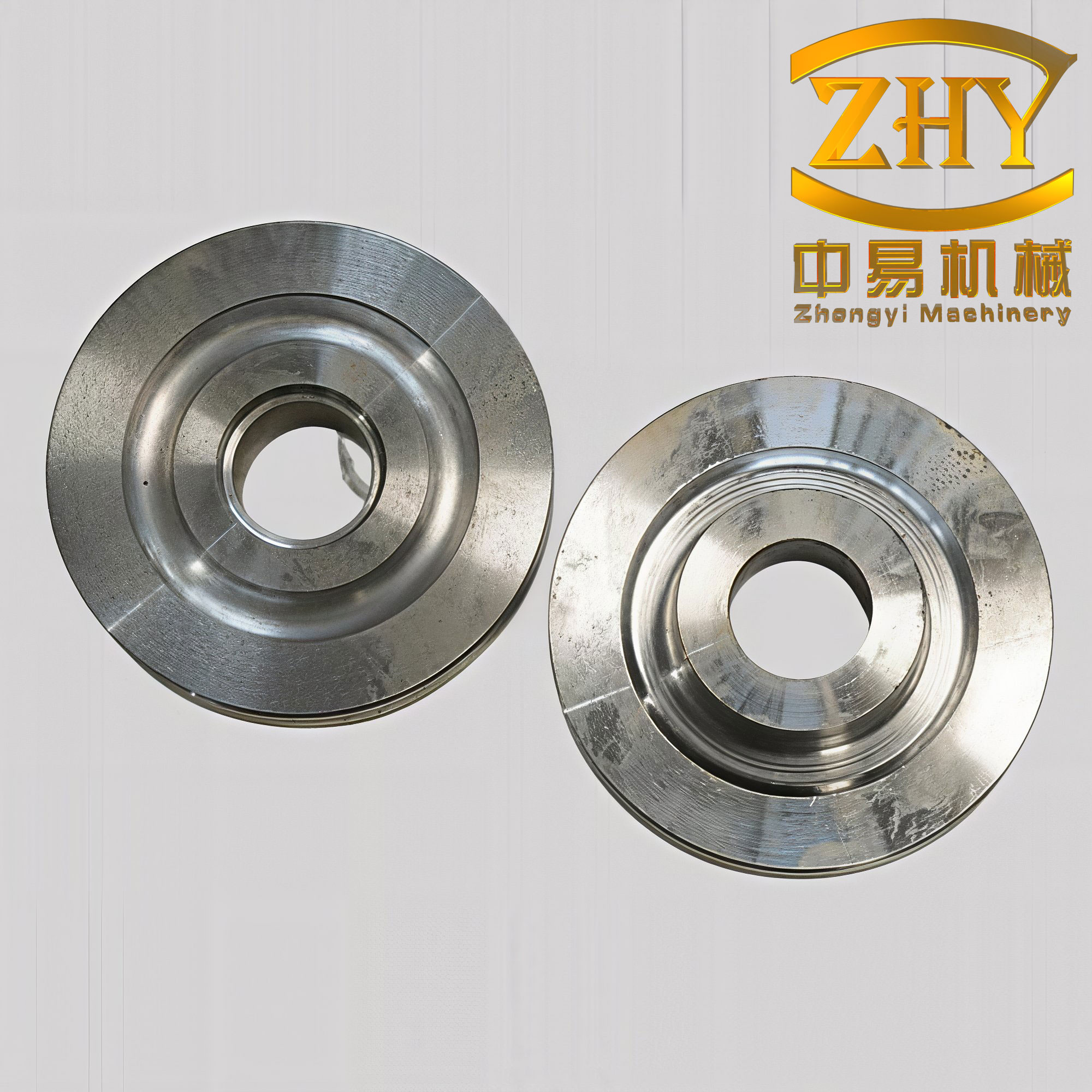
Product Characteristics of Large Forged Gear Blanks
Expanding machines are often used to expand bearing outer rings. The characteristic shape of a bearing ring is that the axial height is greater than the wall thickness. Such parts have good expanding formability. The large forged gear blanks I produced were different. Their radial wall thickness was much greater than the axial height. In some cases, the wall thickness was about twice the axial height. This shape is much more difficult to expand.
Let \(B\) be the axial height and \(T\) be the radial wall thickness. For a bearing-type ring:
$$ B > T $$
For the large forged gear blanks in my work:
$$ T \gg B $$
and in some extreme cases:
$$ T \approx 2B $$
Under these conditions, the forged gear blank often developed grooves on the surface and produced burrs. The burrs were not easy to remove, and they could press into the forging and cause scrap. This became a key problem. After many trials, I modified the dies, controlled the initial blank dimensions, and adjusted the basic parameters of the pressure roll and signal roll. The result was that the burrs were cut off during deformation, the surface quality improved, and a more satisfactory forged gear blank could be rolled.
| Shape feature | Bearing-type ring | Large forged gear blank |
|---|---|---|
| Axial height \(B\) | Relatively large | Relatively small |
| Wall thickness \(T\) | Relatively small | Relatively large |
| Typical relation | \(B > T\) | \(T \gg B\), sometimes \(T \approx 2B\) |
| Formability by expanding | Good | Difficult |
| Common defect | Minor ovality | Grooves, burrs, surface damage |
| Main correction | Normal roll control | Die modification, blank sizing, pressure and signal roll tuning |
The process has now been used for batch production of large forged gear blanks such as differential drive gears, final drive gears, and ring gears for tractors. The important lesson is that a forged gear blank with a thick wall and a short axial height requires a different strategy from a bearing ring. The axial flow must be restrained, the radial flow must be encouraged, and the burr must be controlled at the moment it forms.
Process Comparison for Forged Gear Blanks
I compared the expanding process with the older forging route. The older route relied heavily on free forging hammers for upsetting, piercing, and finishing. The newer route uses a free forging hammer for upsetting and piercing, followed by expanding on the expanding machine. In some cases, a final forging step is still used after expanding. The differences in material use, labor, and quality are significant.
| Item | Old forging route for forged gear blank | Expanding route for forged gear blank |
|---|---|---|
| Main equipment | Free forging hammer, piercing, finishing | Free forging hammer for piercing, expanding machine for ring growth |
| Forming principle | Discontinuous hammer blows | Continuous local rolling |
| Material consumption | Higher | Lower |
| Material utilization | Lower | Higher |
| Labor intensity | High | Lower, with mechanized handling |
| Working conditions | High heat exposure, heavy manual work | Remote operation, reduced heat exposure |
| Machining allowance | Larger | Smaller |
| Tool consumption | Higher in later machining | Reduced in later machining |
| Blank quality | Variable | More uniform forged gear blank |
| Production efficiency | Lower | Higher |
The material utilization of a forged gear blank can be calculated as:
$$ \eta = \frac{m_f}{m_b} \times 100\% $$
where \(m_f\) is the finished forged gear blank mass and \(m_b\) is the billet mass. When I use expanding, the forged gear blank is closer to the final shape, so \(m_b\) can be reduced and \(\eta\) increases. This is one of the strongest economic reasons for using expanding on large forged gear blanks.
The material saving per unit can be written as:
$$ \Delta m = m_{b,old} – m_{b,new} $$
For a family of forged gear blanks, the annual saving is:
$$ S_{year} = N \Delta m $$
where \(N\) is the annual production quantity. Even a small reduction in billet mass becomes significant when the forged gear blank is large and produced in batch quantities.
Defect Mechanisms and Parameter Optimization
When I first expanded thick-walled, short-height forged gear blanks, the main defects were grooves, burrs, and surface damage. These defects did not come from one cause. They came from the interaction of roll geometry, blank volume, temperature, friction, and the timing of the pressure roll and signal roll.
Grooves usually appear when the metal flow is unstable. If the pressure roll forces the forged gear blank against the main roll too strongly, the axial flow is restricted and the radial flow becomes uneven. If the pressure roll force is too low, the forged gear blank can slip or become oval. I found that the pressure roll must be set so that it stabilizes the forged gear blank without blocking radial growth.
Burns form when excess metal is pushed outward or sideways instead of being absorbed into the growing ring. For a forged gear blank with \(T \gg B\), the axial height is short and the wall is thick. The metal has a strong tendency to form a lip at the edges. I modified the die geometry so that this lip is sheared or cut off during deformation. The key is to let the burr form in a controlled location and then remove it by the roll action rather than leaving it on the finished forged gear blank.
| Defect | Probable cause | Correction for forged gear blank |
|---|---|---|
| Surface groove | Unstable metal flow, excessive pressure roll force, poor roll alignment | Adjust pressure roll, align rolls, modify die radius |
| Burr at edge | Excess volume, axial flow, wrong blank height | Reduce billet volume, modify die edge, control axial clearance |
| Ovality | Insufficient support, low rolling speed, asymmetrical heating | Increase support, adjust speed, improve furnace uniformity |
| Lap | Over-reduction per pass, poor contact geometry | Reduce radial reduction, increase roll diameter, adjust feed |
| Incomplete growth | Low force, low temperature, wrong initial volume | Increase force, control temperature, resize billet |
| Signal error | Wrong signal roll setting, thermal growth | Calibrate signal roll, compensate for temperature |
The radial reduction per pass can be expressed as:
$$ \Delta h = h_{in} – h_{out} $$
The total wall reduction is:
$$ \Delta t = t_0 – t_f $$
If the reduction is distributed over \(N_p\) passes, then the average reduction per pass is:
$$ \Delta h_{avg} = \frac{\Delta t}{N_p} $$
I try to keep \(\Delta h_{avg}\) within a range that satisfies the bite condition and avoids excessive burr formation. For a forged gear blank with a thick wall, this range is narrower than for a thin-walled bearing ring.
The temperature of the forged gear blank also matters. The flow stress decreases as temperature increases, but too high a temperature can cause grain growth and surface oxidation. A simple temperature-dependent flow stress model is:
$$ \sigma_f = \sigma_0 \exp\left( \frac{Q}{RT} \right) $$
where \(\sigma_f\) is flow stress, \(Q\) is an activation energy, \(R\) is the gas constant, and \(T\) is absolute temperature. In practice, I do not use this equation directly on the shop floor, but it explains why the same roll setting can produce different results when the forged gear blank temperature changes.
Quality Control of Expanded Forged Gear Blanks
Quality control for a forged gear blank begins before expanding. The billet must have the correct mass, the pierced hole must be centered, and the initial height must be controlled. If the initial volume is too large, the forged gear blank will produce burrs. If it is too small, the final diameter will not be reached. I therefore treat the initial blank as a precision input, not as a rough preparation.
The outer diameter of the forged gear blank after expanding is checked against the target:
$$ D_f = D_{target} \pm \Delta D_{tol} $$
The wall thickness is checked at several points:
$$ t_i = R_{o,i} – R_{i,i} $$
The wall thickness variation is:
$$ \delta_t = t_{\max} – t_{\min} $$
Roundness error is:
$$ \delta_r = D_{\max} – D_{\min} $$
For a good forged gear blank, \(\delta_t\) and \(\delta_r\) must be kept within limits. The signal roll controls the final outer diameter, but it cannot correct an oval or off-center forged gear blank. That is why the passive roll, pressure roll, and blank centering must all be correct.
| Inspection item | Symbol | Purpose for forged gear blank |
|---|---|---|
| Outer diameter | \(D_o\) | Ensures final ring size. |
| Inner diameter | \(D_i\) | Ensures wall thickness after expanding. |
| Axial height | \(B\) | Controls volume and later forging. |
| Wall thickness variation | \(\delta_t\) | Detects ovality and off-center flow. |
| Roundness error | \(\delta_r\) | Indicates roll alignment and support quality. |
| Surface condition | Visual | Detects grooves, laps, and burrs. |
| Temperature | \(T\) | Controls flow stress and final dimensions. |
I also record the expanding cycle time, the main roll pressure, and the signal roll position. These records allow me to trace a forged gear blank back to its process conditions if a problem appears later in machining or final forging.
Mechanization, Safety, and Remote Operation
One of the most practical improvements I made was to change the expanding machine to a front-facing remote operating position. The operator stands about several meters from the machine. This distance allows accurate observation of the signal and better control of the cycle. It also protects the operator from high-temperature radiation. In my installation, one operator can run the expanding cycle for large forged gear blanks, and the handling system reduces direct contact with the hot part.
Safety around a forged gear blank is not only about heat. The expanding machine stores energy in the rotating rolls, the hydraulic or pneumatic cylinder, and the moving slider. A forged gear blank with a large diameter also has significant kinetic energy if it is ejected or dropped. Guards, interlocks, and proper procedure are therefore necessary.
| Hazard | Control method | Benefit for forged gear blank operation |
|---|---|---|
| Heat radiation | Remote operating position | Reduces operator heat exposure. |
| Hot billet handling | Mechanized car, roller table, chute | Reduces manual handling of forged gear blanks. |
| Moving rolls | Guards and interlocks | Prevents contact during expanding. |
| Ejection | Pull rod and inclined chute | Controls part removal after expansion. |
| Overload | Pressure control and signal control | Protects machine and forged gear blank. |
The remote position also improves process control. I can see the signal roll, the main roll, and the forged gear blank clearly. If the forged gear blank begins to slip, I can stop the cycle before a serious defect forms. This is difficult when the operator is too close to the machine or has a poor view.
Problems and Future Development for Forged Gear Blanks
From the standpoint of equipment structure and part strength, the expanding machine I used is somewhat weak for large forged gear blanks. This is especially true for the transmission parts, such as universal joints and shafts. However, as operating skill improved, the service life of these parts increased significantly. The machine is not a heavy die-forging press, and it must be treated with respect.
The reduction gearbox has also been considered unnecessary. When expanding large forged gear blanks, a rotational speed in a relatively narrow range is ideal. For many large forged gear blanks, one speed is enough. A simpler drive would reduce cost, maintenance, and energy loss. If I were to redesign the machine, I would match the drive speed more closely to the expanding process and remove unnecessary gear stages.
At present, some forged gear blanks, such as a final drive passive gear, still require final forging on a free forging hammer after expanding. The future target is to form the forged gear blank in one pass on the expanding machine and reduce the machining allowance to a minimum. I have made repeated trials toward this goal, and the results were encouraging. The once-formed forged gear blank can be produced, but it has not yet been put into full production because of die and process factors.
| Current limitation | Future improvement | Expected effect on forged gear blank |
|---|---|---|
| Transmission parts are weak | Increase shaft and universal joint capacity | Longer machine life when rolling large forged gear blanks. |
| Gearbox is redundant | Use a single optimal speed | Lower cost and simpler maintenance. |
| Some parts need final hammer forging | One-pass expanding to final shape | Shorter process route for the forged gear blank. |
| Machining allowance still present | Precision roll and die control | Less material waste in the forged gear blank. |
| Manual adjustments remain | Automated signal and pressure control | More consistent forged gear blank dimensions. |
| Die life variation | Better cooling, lubrication, and die material | Stable surface quality on forged gear blanks. |
The future direction is not simply to make the machine bigger. It is to make the process more precise. A large forged gear blank is expensive, and a defective forged gear blank wastes heat, labor, and material. By controlling the initial volume, the pressure roll, the signal roll, and the thermal cycle, I can make the expanding process repeatable.
Additional Process Calculations for Forged Gear Blanks
To support process design, I often use several additional relationships. The final outer diameter of the forged gear blank after expanding can be estimated from volume constancy and the final wall thickness. Starting from:
$$ V_0 = \pi \left( R_{o0}^2 – R_{i0}^2 \right) B_0 $$
and
$$ V_f = \pi \left( R_{of}^2 – R_{if}^2 \right) B_f $$
If \(V_0 = V_f\), then:
$$ R_{of}^2 – R_{if}^2 = \frac{B_0}{B_f} \left( R_{o0}^2 – R_{i0}^2 \right) $$
If the height is constant, \(B_0/B_f = 1\), and:
$$ R_{of}^2 – R_{if}^2 = R_{o0}^2 – R_{i0}^2 $$
The final wall thickness is:
$$ t_f = R_{of} – R_{if} $$
The mandrel or inner roll diameter affects the inner radius. If the inner radius is fixed by the mandrel, then the outer radius grows according to:
$$ R_{of} = \sqrt{R_{if}^2 + R_{o0}^2 – R_{i0}^2} $$
This equation is useful when I want to know whether a given initial pierced hole can produce the required forged gear blank.
The strain in the wall thickness direction can be approximated as:
$$ \varepsilon_t = \ln\left( \frac{t_f}{t_0} \right) $$
The hoop strain at the outer surface is:
$$ \varepsilon_\theta = \ln\left( \frac{R_{of}}{R_{o0}} \right) $$
The axial strain is:
$$ \varepsilon_B = \ln\left( \frac{B_f}{B_0} \right) $$
For volume constancy in plastic deformation:
$$ \varepsilon_t + \varepsilon_\theta + \varepsilon_B \approx 0 $$
These equations help me understand why a thick-walled forged gear blank behaves differently from a thin-walled ring. When \(t\) is large relative to \(B\), the axial strain is small and the hoop strain is large. The material must flow mostly in the circumferential direction. If the roll geometry forces axial flow, defects appear.
| Quantity | Formula | Use in forged gear blank control |
|---|---|---|
| Volume | \(V = \pi (R_o^2 – R_i^2)B\) | Checks initial and final size. |
| Wall thickness | \(t = R_o – R_i\) | Sets reduction target. |
| Reduction ratio | \(\varepsilon_t = (t_0 – t_f)/t_0\) | Controls deformation severity. |
| Rolling speed | \(v = \pi D_r n / 60\) | Sets production rate. |
| Contact length | \(L_c \approx \sqrt{R_r \Delta h}\) | Estimates bite and pressure. |
| Material utilization | \(\eta = m_f/m_b\) | Measures material saving. |
| Annual saving | \(S_{year} = N \Delta m\) | Evaluates economic benefit. |
Practical Operating Rules for Forged Gear Blanks
Over time, I developed a set of practical rules for expanding forged gear blanks. These rules are not a substitute for calculations, but they help avoid common mistakes.
First, the initial forged gear blank must be centered. If the pierced hole is off-center, the wall thickness will vary, and the signal roll will stop the cycle when one side is correct while the other side is still undersized.
Second, the pressure roll must be set to stabilize, not to crush. A pressure roll that is too aggressive will create axial flow and burrs. A pressure roll that is too loose will allow slipping and ovality.
Third, the signal roll must be calibrated for the actual hot size of the forged gear blank. Thermal contraction after expanding means the cold size is smaller than the hot size. If the signal roll is set to the cold target, the hot forged gear blank may be too large after cooling.
Fourth, the main roll speed should be chosen to match the wall reduction. If the speed is too high, the forged gear blank may slip. If the speed is too low, the temperature may drop and the flow stress may rise.
Fifth, lubrication and cooling must be consistent. Uneven cooling can cause uneven deformation and surface defects on the forged gear blank.
| Rule | Reason | Result for forged gear blank |
|---|---|---|
| Center the initial hole | Controls wall variation | Uniform wall thickness. |
| Set pressure roll to stabilize | Prevents axial flow and slip | Fewer grooves and burrs. |
| Calibrate signal roll hot | Compensates thermal contraction | Correct cold size. |
| Match speed to reduction | Maintains bite and temperature | Stable expanding cycle. |
| Control cooling and lubrication | Reduces thermal gradients | Better surface quality. |
| Record every setup | Enables traceability | Repeatable forged gear blank quality. |
Economic and Production Effects of Expanding Forged Gear Blanks
The economic effect of expanding is not limited to material saving. It also changes the whole production flow. A forged gear blank that is closer to final shape requires less machining. Less machining means fewer cutting tools, less electricity, and less labor. The hot working department also becomes less dependent on repeated hammer blows.
If the old process requires a billet mass \(m_{b,old}\) and the new process requires \(m_{b,new}\), the material saving ratio is:
$$ R_m = \frac{m_{b,old} – m_{b,new}}{m_{b,old}} \times 100\% $$
The increase in material utilization is:
$$ \Delta \eta = \eta_{new} – \eta_{old} $$
The reduction in machining hours can be written as:
$$ \Delta T_{mach} = T_{mach,old} – T_{mach,new} $$
For a batch of \(N\) forged gear blanks, the total machining time saving is:
$$ S_{mach} = N \Delta T_{mach} $$
These values are important when justifying the expanding machine for a new forged gear blank family. The machine may be non-standard, but the savings accumulate over many parts.
| Economic factor | Old route | Expanding route |
|---|---|---|
| Steel consumption per tractor | Higher | Lower |
| Material utilization | Lower | Higher |
| Hot working time | Longer | Shorter |
| Cold machining time | Longer | Shorter |
| Tool consumption | Higher | Lower |
| Labor condition | Heavy and hot | Mechanized and remote |
| Forged gear blank quality | Variable | More uniform |
In my experience, the expanding process is especially effective when the forged gear blank is large and the annual quantity is high. The initial trials may require careful adjustment, but once the process window is established, the cycle is repeatable. The forged gear blank becomes a controlled ring rather than a rough hammered shape.
Concluding Observations on Forged Gear Blanks
I have found that expanding is a practical and efficient method for producing large forged gear blanks, especially annular gear blanks that are difficult to form by ordinary forging. The process offers high productivity, better working conditions, improved blank quality, lower material consumption, and lower equipment investment. The expanding machine is easier to manufacture than die-forging equipment and is easier to mechanize.
The main challenge is the shape of the forged gear blank. When the wall thickness is much greater than the axial height, the metal flow is unfavorable. Grooves and burrs can form, and they can damage the forged gear blank. By modifying dies, controlling the initial blank size, and adjusting the pressure roll and signal roll, I was able to control the burr and improve the surface. The expanding process has been used successfully for batch production of large forged gear blanks for tractors.
The machine still has limitations. The transmission can be weak for very large forged gear blanks, and the gearbox may be unnecessary if a single optimal speed is chosen. Some forged gear blanks still require final forging after expanding. The future goal is one-pass forming on the expanding machine with minimum allowance. Trials have been encouraging. With further development in die design, control systems, and mechanization, expanding will become an even stronger method for producing large forged gear blanks.