
In modern manufacturing, CNC machine tools serve as the backbone of industries such as aerospace, automotive, and defense. Among these, spiral bevel gears are critical components due to their advantages in smooth transmission, low noise, and high load capacity. The precision of gear milling directly impacts the performance of mechanical products, making it imperative to enhance the machining accuracy of CNC spiral bevel gear milling machines. This study focuses on developing a real-time geometric error compensation system for such machines, with the aim of improving their overall precision. I will explore the error sources, establish compensation models, design a real-time compensation system, and validate it through simulations and experimental testing on a triaxial micro-milling platform.
The development of gear milling machines has evolved significantly. Internationally, companies like Gleason have pioneered CNC-based gear milling technologies, such as the Phoenix series, which incorporate five-axis联动 and advanced control systems. Domestically, progress has been made with machines like the YKA2260, yet challenges remain in achieving high precision due to error factors. Error compensation techniques offer a cost-effective solution by mitigating errors rather than solely relying on hardware improvements. This research addresses the need for precision enhancement in gear milling by focusing on geometric error compensation, which constitutes a significant portion of overall machine tool errors.
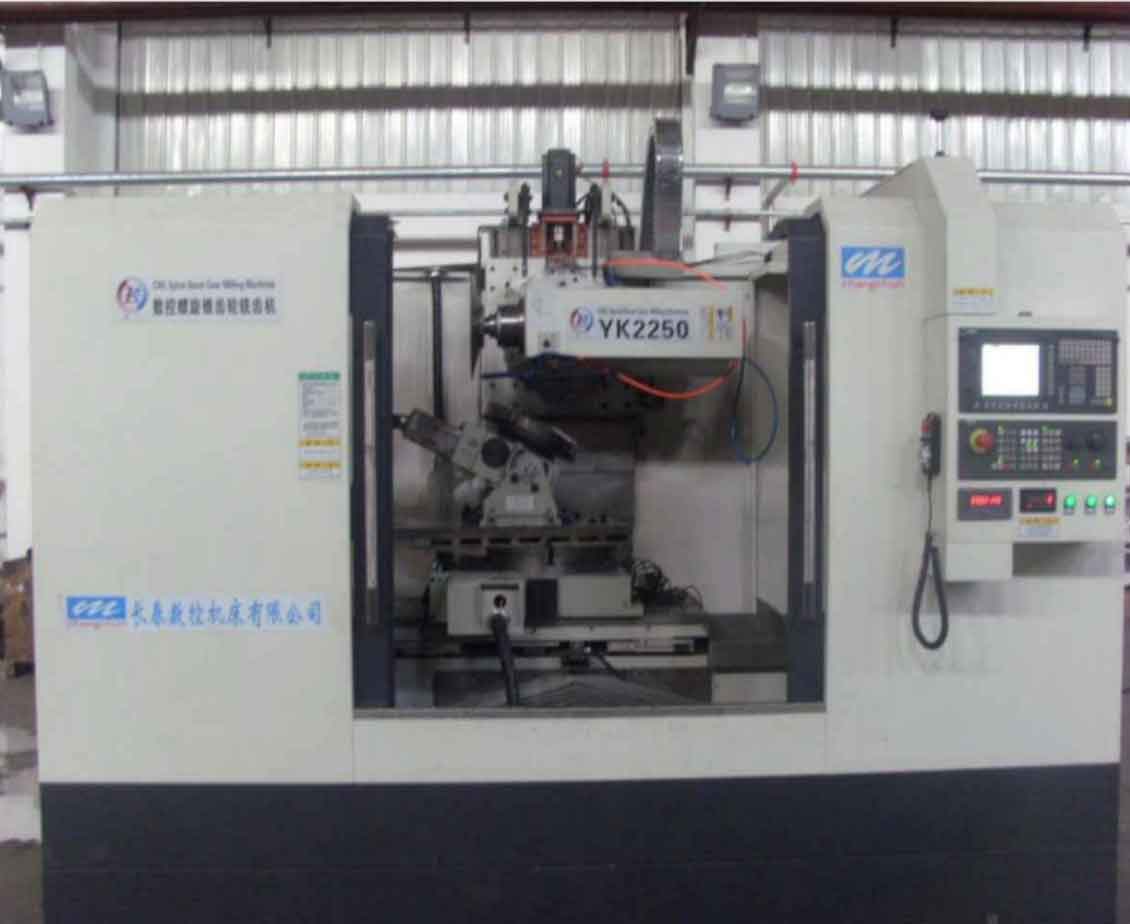
Error sources in CNC machine tools can be categorized into static, steady-state, and dynamic errors. For gear milling machines, static geometric errors are predominant, arising from manufacturing and assembly inaccuracies. These errors include positioning errors, straightness errors, and rotational errors, which degrade the accuracy of gear milling processes. I analyze these geometric error elements in detail to identify the key compensable factors. The gear milling machine studied here is a double-turntable five-axis CNC machine with three linear axes (X, Y, Z) and two rotational axes (A, C). Its motion model involves coordinated movements to achieve precise gear milling, but geometric deviations introduce errors that must be compensated.
To systematically address these errors, I first establish a table of geometric error elements for the gear milling machine. This table includes error symbols and descriptions for moving pairs (e.g., linear axes) and rotational pairs. For instance, positioning errors along the X-axis are denoted as $$ \delta_{xx} $$, representing the deviation between actual and commanded positions during gear milling. Similarly, straightness errors, such as $$ \delta_{yx} $$ for Y-direction straightness during X-axis movement, and rotational errors, like $$ \varepsilon_{yx} $$ for pitch error during X-axis movement, are considered. A total of 26 geometric error elements are identified for compensation, as summarized in the table below.
| Motion Direction | X-axis | Y-axis | Z-axis | Error Source |
|---|---|---|---|---|
| X-direction Translation | $$ \delta_{xx} $$ | $$ \delta_{xy} $$ | $$ \delta_{xz} $$ | Geometric (G) |
| Y-direction Translation | $$ \delta_{yx} $$ | $$ \delta_{yy} $$ | $$ \delta_{yz} $$ | Geometric (G) |
| Z-direction Translation | $$ \delta_{zx} $$ | $$ \delta_{zy} $$ | $$ \delta_{zz} $$ | Geometric (G) |
| Rotational Errors | $$ \varepsilon_{xx}, \varepsilon_{yx}, \varepsilon_{zx} $$ | $$ \varepsilon_{xy}, \varepsilon_{yy}, \varepsilon_{zy} $$ | $$ \varepsilon_{xz}, \varepsilon_{yz}, \varepsilon_{zz} $$ | Geometric (G) |
Based on this analysis, I develop a comprehensive mathematical model for error compensation. For a double-turntable five-axis gear milling machine, the error compensation model utilizes homogeneous transformation matrices (HTM) to account for geometric deviations. The model expresses the tool-workpiece position error as a function of basic error elements. The general form for the error matrix $$ E $$ is given by:
$$ E = \begin{bmatrix} 1 & -\varepsilon_{zq} & \varepsilon_{yq} & \delta_{xq} \\ \varepsilon_{zq} & 1 & -\varepsilon_{xq} & \delta_{yq} \\ -\varepsilon_{yq} & \varepsilon_{xq} & 1 & \delta_{zq} \\ 0 & 0 & 0 & 1 \end{bmatrix} $$
where $$ \delta_{xq}, \delta_{yq}, \delta_{zq} $$ represent positional errors, and $$ \varepsilon_{xq}, \varepsilon_{yq}, \varepsilon_{zq} $$ represent angular errors. The overall displacement errors $$ \Delta x, \Delta y, \Delta z $$ are computed from the transformation between the workpiece and tool coordinates, enabling compensation by applying opposite motion amounts. For interpolation between compensation points, I employ third-order spline interpolation to ensure smooth transitions during gear milling. The spline function $$ S(x) $$ satisfies continuity conditions for position and derivatives, enhancing compensation accuracy compared to linear interpolation.
With the error model established, I design a real-time error compensation system. Error compensation methods include closed-loop feedback, open-loop feedforward, and semi-closed loop systems. For gear milling machines, I choose a closed-loop feedback compensation system due to its high precision, coupled with a feedback interruption strategy that inserts compensation signals into the servo feedback loop. This approach is universally applicable and does not modify the original CNC programs. The system hardware consists of an Industrial Personal Computer (IPC) as the main control center and a Programmable Multi-Axis Controller (PMAC) for real-time control, communicating via EtherCAT protocol for fast and reliable data exchange. The software interface, developed using PMAC IDE, allows for monitoring and managing compensation processes during gear milling.
The system is modularized into seven functional modules: error calculation, data import/export, machine status monitoring, system information query, parameter setting, PMAC data storage and activation, and PMAC real-time invocation. These modules facilitate tasks such as storing error compensation data, calculating compensation values, and dynamically allocating memory for real-time operations. The compensation workflow involves preparing error data through measurement devices like laser interferometers, computing compensation values using the mathematical model, and activating compensation during gear milling operations. Data is前瞻 buffered to ensure seamless compensation along the tool path, with buffer size optimized based on compensation length and computation time.
To validate the compensation system, I conduct simulation experiments using a modular approach. The servo system is simulated with components like coordinate transformation modules (Park, Anti-Park, Clark), SPWM modules, and a three-loop control structure (position, speed, current loops) with PID controllers. The controller module simulates PMAC functionality for data storage and interpolation. I focus on compensating positioning errors, such as pitch error and backlash, as representative geometric error elements in gear milling. The simulation model integrates these modules, and results are observed via oscilloscope outputs. For example, without compensation, the actual position deviates from the commanded position; with compensation, the actual position aligns with the commanded position, confirming system feasibility. The simulation equations for PID control include proportional gain $$ K_p $$, integral gain $$ K_i $$, and derivative gain $$ K_d $$, tuned to optimize dynamic response.
Following simulation, I perform functional testing on a triaxial micro-milling platform, which mirrors the gear milling machine’s control system. The platform includes an IPC, PMAC controller, Servotronix servo drives and motors, a cross-slide for limit setting, and a handwheel for manual control. System configuration involves setting up EtherCAT communication, motor parameters, and compensation files in PMAC. To enhance performance, I apply a feedforward-plus-feedback PID algorithm, tuning gains such as $$ K_{vff} $$ for velocity feedforward and $$ K_{aff} $$ for acceleration feedforward. The tuning process involves open-loop tests, step response adjustments, parabolic signal tuning, and sinusoidal sweep validation, reducing root-mean-square (RMS) following error by over 90% for improved gear milling accuracy.
Experiments test various compensation functions, including pitch error compensation, backlash compensation, straightness compensation, flatness compensation, and协同 compensation. Evaluation metrics are monitored via PMAC IDE plotting功能, such as actual position $$ \text{Motor}[x].\text{ActPosition} $$, compensation value $$ \text{Motor}[x].\text{CompPos} $$, and backlash size $$ \text{Motor}[x].\text{BlSize} $$. For pitch error compensation, results show that the sum of uncompensated position and compensation value equals the actual position, with third-order spline interpolation ensuring smooth transitions. Backlash compensation similarly verifies effectiveness by aligning actual positions with commanded positions after补偿. Straightness and flatness compensations, referencing other axes, also demonstrate successful error reduction.协同 compensation of pitch and backlash errors further confirms system capability to handle multiple error sources simultaneously during gear milling.
In conclusion, this research develops a comprehensive geometric error compensation solution for CNC spiral bevel gear milling machines. By analyzing error sources, establishing a mathematical model, designing a real-time compensation system, and validating through simulations and tests, I demonstrate that the proposed approach effectively enhances machining precision. The system leverages closed-loop feedback and EtherCAT communication to achieve real-time compensation for key geometric errors, such as positioning and straightness errors, which are critical in gear milling processes. Future work could extend to thermal error compensation and more tailored error models for specific gear milling applications. Overall, this study contributes to advancing precision manufacturing in the gear milling industry, offering a practical and cost-effective method for error mitigation.