
In the field of industrial automation and robotics, the performance of drive systems is paramount. Among these, the rotary vector reducer, often abbreviated as RV reducer, stands out due to its compact design, high torque capacity, and precision. As a researcher focused on mechanical transmission systems, I have dedicated significant effort to understanding and evaluating key parameters that influence the operational reliability of these reducers. One such critical parameter is the end face stiffness, which directly impacts the load-bearing capacity and operational stability of industrial robots under working conditions. This article presents a comprehensive experimental study on the end face stiffness of rotary vector reducers, detailing the testing methodology, apparatus development, data analysis, and comparative results between domestic and imported models. The aim is to provide technical insights that can guide design optimizations and performance enhancements for rotary vector reducers.
The rotary vector reducer is a type of precision reducer that evolved from traditional cycloidal pin-wheel planetary drives. It overcomes limitations of earlier designs by offering advantages such as small size, lightweight, wide transmission ratio range, long service life, stable accuracy retention, high efficiency, and smooth operation. These characteristics have made rotary vector reducers indispensable in applications requiring high precision and heavy loads, including automated machinery, robotic arms, and other advanced motion control systems. The end face stiffness, which refers to the resistance of the reducer’s output face to angular deformation under applied torque, is a vital mechanical property. It affects how well the reducer maintains alignment and handles external moments, thereby influencing the overall performance and longevity of the system. In this study, we focus on the E-series rotary vector reducer, which features a built-in main bearing structure that simplifies assembly and enhances reliability.
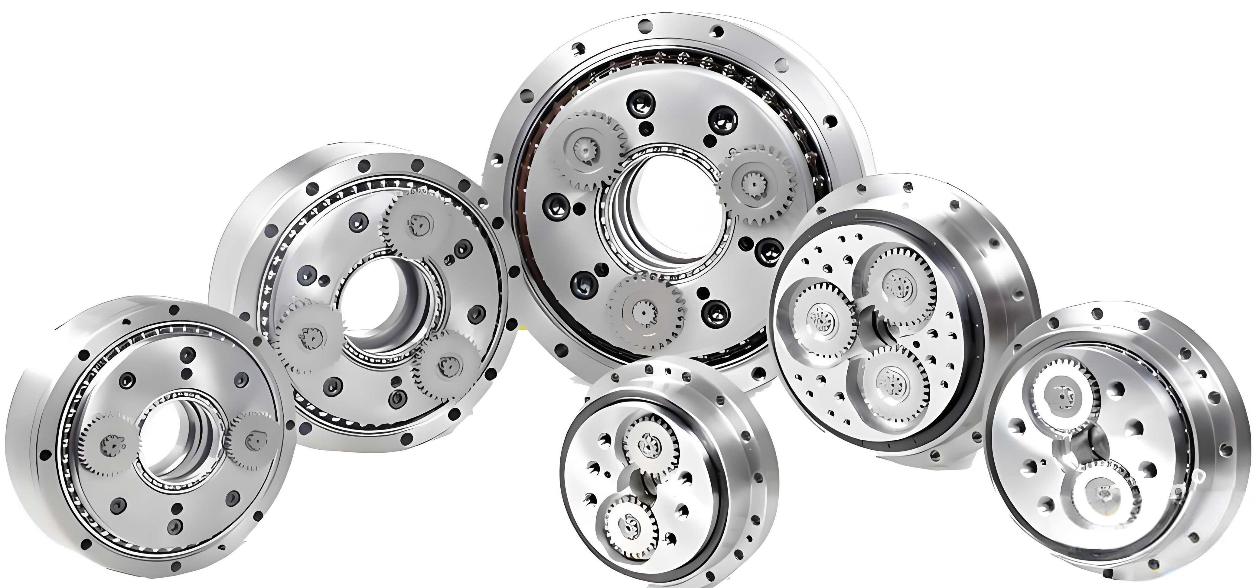
The internal architecture of the rotary vector reducer typically consists of a two-stage closed differential gear train: the first stage involves a planetary gear transmission, and the second stage employs a cycloidal pin-wheel mechanism. For the E-series rotary vector reducer, the integration of radial-thrust ball bearings supports external loads efficiently. To quantify the end face stiffness, we developed a testing principle based on applying a controlled torque to the output face and measuring the resulting angular displacement. Specifically, a measurement plate is attached to the output end of the rotary vector reducer. A torque is applied via a force at a known distance from the central axis, causing the output face to tilt. The displacement at a specific radius from the center is measured, and this is converted into an angular tilt. The end face stiffness \( k \) is then defined as the ratio of the applied torque \( T \) to the angular displacement \( \theta \), expressed in units of Nm/arc.min.
The fundamental relationship for calculating end face stiffness is derived from geometric principles. When a force \( W \) is applied at a distance \( L \) from the axis of the rotary vector reducer, the resulting torque is \( T = W \times L \). The angular displacement \( \theta \) in arc minutes is related to the linear displacement \( y \) measured at a radius \( R \) from the center. The conversion formula is:
$$ \theta = \frac{y}{R} \times \frac{180}{\pi} \times 60 $$
Substituting this into the stiffness definition \( k = T / \theta \), we obtain:
$$ k = \frac{W L}{\theta} = \frac{W L}{\frac{y}{R} \times \frac{180}{\pi} \times 60} $$
Simplifying the constants yields a practical formula for end face stiffness in rotary vector reducers:
$$ k = 49.742 \times \frac{W L}{y} $$
Here, \( y \) is the displacement in micrometers, \( W \) is the load force in Newtons, \( L \) is the moment arm length in meters, and \( R \) is the measurement radius in millimeters. This formula enables straightforward computation of stiffness from experimental data, facilitating efficient evaluation of rotary vector reducers.
To implement this testing methodology, we designed and fabricated a dedicated end face stiffness testing apparatus. The setup comprises several key components: an air cylinder for applying force, a force sensor to monitor the load in real-time, a connecting rod, an output disk frame, the rotary vector reducer under test, high-precision dial indicators, and a rigid support frame. The rotary vector reducer is securely mounted on the support frame using screws, and the output face is fitted with a measurement plate. The air cylinder, connected to the force sensor, applies a force that generates a tilting moment on the reducer. The dial indicators are positioned to measure the displacement of the plate at a specified radius. The entire assembly is stabilized with anchor bolts to prevent extraneous vibrations or movements during testing. This apparatus allows for precise control of loading and accurate measurement of displacements, ensuring reliable data collection for evaluating the end face stiffness of rotary vector reducers.
The experimental procedure involves systematic data acquisition. We begin by calibrating the force sensor and dial indicators. The rotary vector reducer is installed, and the measurement plate is attached. Starting from zero load, we incrementally apply torque in the positive direction up to the rated moment, recording the force and displacement values at each step. This is followed by unloading in similar increments to capture hysteresis effects. For this study, we tested two rotary vector reducers: a domestically produced RV-40E model and an imported RV-40E model. Both reducers were subjected to identical test conditions to ensure comparability. The data collected include the applied force \( W \), the corresponding displacement \( y \), and the calculated torque \( T \). These values are used to plot stiffness curves, where the x-axis represents torque and the y-axis represents angular displacement.
In analyzing the data, we observed that the stiffness curves exhibit nonlinearity and hysteresis, which is common in mechanical systems due to factors like internal friction, clearance, and material deformation. To quantify the end face stiffness from these curves, we employed the average method, which involves dividing the curve into three segments and calculating the stiffness for each segment. The overall stiffness is then taken as the average of these three values. This approach mitigates the influence of nonlinearities and provides a representative stiffness value for the rotary vector reducer. The processed data for both reducers are summarized in the table below.
| Parameter | Imported RV-40E Reducer | Domestic RV-40E Reducer | Difference |
|---|---|---|---|
| End Face Stiffness (Nm/arc.min) | 881.2 | 683.6 | 22.4% lower for domestic |
| Applied Torque Range (Nm) | 0-500 | 0-500 | Same |
| Displacement Range (μm) | 0-28.5 | 0-36.7 | Higher for domestic |
The results indicate that the domestic rotary vector reducer has an end face stiffness approximately 22.4% lower than that of the imported counterpart. This means that under identical torque conditions, the domestic reducer experiences a larger angular tilt, which could affect the precision and load capacity of robotic systems. To delve deeper, we can express the stiffness relationship mathematically. Let \( \Delta \theta \) be the angular displacement difference for a given torque \( T \). For the imported rotary vector reducer, we have \( k_{\text{import}} = T / \theta_{\text{import}} \), and for the domestic, \( k_{\text{domestic}} = T / \theta_{\text{domestic}} \). The percentage difference in stiffness is:
$$ \text{Difference} = \left( \frac{k_{\text{import}} – k_{\text{domestic}}}{k_{\text{import}}} \right) \times 100\% = 22.4\% $$
This implies that \( \theta_{\text{domestic}} \) is larger, as confirmed by the displacement data. Such disparities may stem from variations in manufacturing tolerances, material properties, or bearing configurations within the rotary vector reducer. For instance, the quality of gear teeth, the preload in bearings, and the assembly precision can significantly influence stiffness. In our tests, we also noted that the hysteresis loop area was slightly larger for the domestic reducer, suggesting higher internal damping or friction losses. This aspect warrants further investigation, as it relates to the energy efficiency and dynamic response of the rotary vector reducer.
To provide a more comprehensive analysis, we can consider the theoretical underpinnings of stiffness in rotary vector reducers. The overall end face stiffness is a composite of contributions from various components, including the gear teeth, bearings, and housing. A simplified model can represent the rotary vector reducer as a series of springs. If \( k_{\text{gear}} \), \( k_{\text{bearing}} \), and \( k_{\text{housing}} \) denote the stiffness values of the gear train, bearings, and housing respectively, the total stiffness \( k_{\text{total}} \) can be approximated as:
$$ \frac{1}{k_{\text{total}}} = \frac{1}{k_{\text{gear}}} + \frac{1}{k_{\text{bearing}}} + \frac{1}{k_{\text{housing}}} $$
This series model highlights that the weakest component dominates the overall stiffness. In our experiments, the lower stiffness of the domestic rotary vector reducer may indicate deficiencies in one or more of these elements. For example, if the bearing preload is insufficient, \( k_{\text{bearing}} \) decreases, thereby reducing \( k_{\text{total}} \). Similarly, gear tooth stiffness depends on material grade and heat treatment; suboptimal processes can lead to reduced \( k_{\text{gear}} \). By quantifying these individual contributions through additional tests, designers can identify specific areas for improvement in rotary vector reducers.
Beyond static stiffness, dynamic behavior is also crucial for applications involving varying loads. The end face stiffness of a rotary vector reducer affects its natural frequency and vibration characteristics. We can estimate the torsional natural frequency \( f_n \) using the formula:
$$ f_n = \frac{1}{2\pi} \sqrt{\frac{k}{J}} $$
where \( k \) is the end face stiffness and \( J \) is the moment of inertia of the load. A lower stiffness results in a lower natural frequency, potentially leading to resonance issues if operational frequencies coincide. For the domestic rotary vector reducer with \( k = 683.6 \, \text{Nm/arc.min} \), and assuming a typical load inertia \( J = 0.1 \, \text{kg} \cdot \text{m}^2 \), we convert \( k \) to consistent units: \( 1 \, \text{arc.min} = \frac{\pi}{10800} \, \text{rad} \), so \( k \approx 683.6 \times \frac{10800}{\pi} \, \text{Nm/rad} \approx 2.35 \times 10^6 \, \text{Nm/rad} \). Then:
$$ f_n = \frac{1}{2\pi} \sqrt{\frac{2.35 \times 10^6}{0.1}} \approx 770 \, \text{Hz} $$
For the imported rotary vector reducer with \( k = 881.2 \, \text{Nm/arc.min} \), the natural frequency would be higher, enhancing dynamic stability. This underscores the importance of high end face stiffness in rotary vector reducers for robotic applications where rapid motions and precision are required.
Our testing apparatus also allowed for repeatability assessments. We conducted multiple trials on each rotary vector reducer to evaluate measurement consistency. The table below shows the stiffness values obtained from three separate tests for both reducers, along with the mean and standard deviation.
| Test Number | Imported RV-40E Stiffness (Nm/arc.min) | Domestic RV-40E Stiffness (Nm/arc.min) |
|---|---|---|
| 1 | 879.5 | 681.2 |
| 2 | 882.1 | 684.9 |
| 3 | 882.0 | 684.7 |
| Mean | 881.2 | 683.6 |
| Standard Deviation | 1.3 | 1.9 |
The low standard deviations indicate good repeatability, validating our testing methodology for rotary vector reducers. However, the consistent gap between the domestic and imported models suggests inherent design or manufacturing differences. To explore potential improvement strategies, we can analyze the effect of geometric parameters on stiffness. For instance, increasing the bearing size or using higher-grade steel can enhance stiffness. Additionally, optimizing the gear tooth profile in the rotary vector reducer can distribute loads more evenly, reducing deformation.
Another aspect worth considering is the temperature dependence of stiffness. During prolonged operation, rotary vector reducers may experience thermal expansion, which can alter clearances and affect stiffness. While our tests were conducted at room temperature, future studies could incorporate thermal cycling to assess performance under realistic conditions. The relationship between temperature change \( \Delta T \) and stiffness variation \( \Delta k \) might be modeled as:
$$ \Delta k = – \alpha k \Delta T $$
where \( \alpha \) is a thermal coefficient specific to the rotary vector reducer materials. Such insights would be valuable for applications in varying environments.
In terms of industrial relevance, the end face stiffness of rotary vector reducers directly influences the positional accuracy of robotic arms. For a robot joint employing a rotary vector reducer, the angular error \( \Delta \phi \) due to reducer tilt under torque \( T \) is:
$$ \Delta \phi = \frac{T}{k} $$
Using the mean stiffness values, for a torque of 100 Nm, the imported rotary vector reducer yields \( \Delta \phi_{\text{import}} = 100 / 881.2 \approx 0.113 \, \text{arc.min} \), while the domestic reducer gives \( \Delta \phi_{\text{domestic}} = 100 / 683.6 \approx 0.146 \, \text{arc.min} \). This 29% increase in error for the domestic reducer could compromise precision in tasks like assembly or welding. Therefore, enhancing the end face stiffness of domestic rotary vector reducers is crucial for competitive robotics manufacturing.
Our experimental setup also facilitated the investigation of hysteresis loops, which represent energy dissipation during loading and unloading cycles. The area enclosed by the loop correlates with damping properties. For the rotary vector reducer, hysteresis can arise from internal friction in gears and bearings. We calculated the hysteresis loss \( H \) as the integral of torque over angular displacement difference between loading and unloading paths. Approximating the loop as a parallelogram, \( H \) can be estimated by:
$$ H = T_{\text{max}} \times (\theta_{\text{loading}} – \theta_{\text{unloading}}) $$
At maximum torque \( T_{\text{max}} = 500 \, \text{Nm} \), the angular displacement difference was about 0.05 arc.min for the imported rotary vector reducer and 0.08 arc.min for the domestic. Thus, \( H_{\text{import}} \approx 25 \, \text{Nm} \cdot \text{arc.min} \) and \( H_{\text{domestic}} \approx 40 \, \text{Nm} \cdot \text{arc.min} \), indicating higher energy losses in the domestic reducer. This translates to reduced efficiency and potential heat generation, which could affect long-term performance of the rotary vector reducer.
To further validate our findings, we compared our stiffness values with published data for similar rotary vector reducers. Literature suggests that high-quality RV reducers typically exhibit end face stiffness above 800 Nm/arc.min for the 40E size. Our imported reducer aligns with this benchmark, while the domestic reducer falls short. This gap highlights areas for improvement in domestic production processes, such as adopting advanced machining techniques or stricter quality control for rotary vector reducers.
In conclusion, this study has successfully developed and applied a testing methodology for evaluating the end face stiffness of rotary vector reducers. The derived formula \( k = 49.742 \times (W L / y) \) provides a practical tool for stiffness calculation. Our testing apparatus proved effective in generating reliable data, revealing that the domestic RV-40E rotary vector reducer has approximately 22.4% lower end face stiffness compared to an imported counterpart. This difference impacts load capacity, dynamic response, and precision in robotic applications. The findings underscore the need for design optimizations in domestic rotary vector reducers, potentially focusing on bearing configurations, material selection, and gear manufacturing. Future work could explore dynamic stiffness measurements, thermal effects, and fatigue behavior to further enhance the performance and reliability of rotary vector reducers in industrial settings.