
The relentless pursuit of vehicle lightweighting, stringent emission regulations, and escalating customer demands for refined powertrain behavior and superior noise, vibration, and harshness (NVH) performance have driven the automotive industry towards developing transmission components that are lighter, more efficient, quieter, and more reliable. Among these, the drive axle stands as a pivotal core component within a vehicle’s driveline. It endures complex loading conditions, and its operational performance is intrinsically linked to the overall vehicle’s safety, ride comfort, and dynamic response. Notably, the vibration and noise generated by the drive axle during operation have a profound and direct impact on the vehicle’s overall NVH characteristics. Therefore, suppressing drive axle vibration and noise represents one of the most effective pathways to enhance product competitiveness, constituting a major research focus for both academia and the automotive engineering community globally.
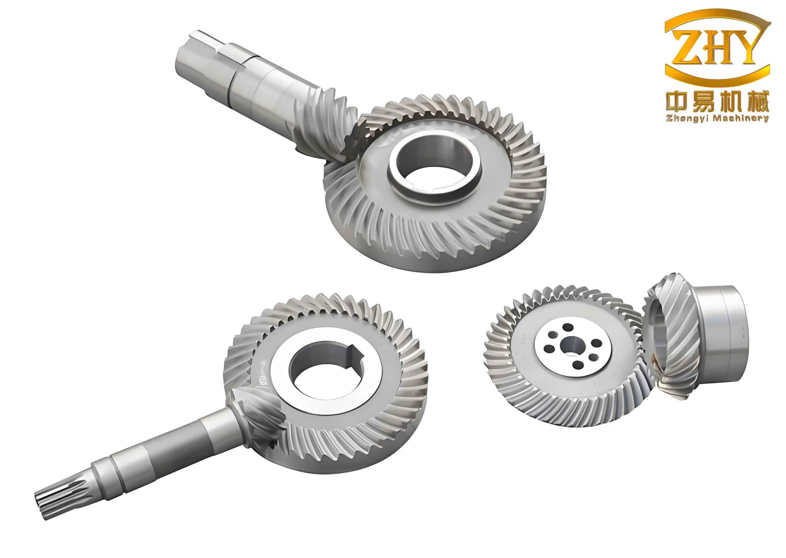
This investigation centers on the hypoid (hyperboloidal) gear pair within the drive axle’s final reduction system. Hypoid gears are favored for their ability to transmit high torque between non-intersecting, offset axes, enabling lower vehicle profiles. However, their complex geometry and meshing action introduce significant dynamic challenges. To master the laws governing vibration response and achieve active control over the drive axle’s dynamic characteristics, it is essential to develop a comprehensive dynamic model. This model must account for the key internal excitations inherent to hyperboloidal gear meshing. Traditional analyses often simplify or neglect certain nonlinear, time-varying factors. This work aims to construct a more holistic multi-factor coupled vibration model for the drive axle’s gear transmission system, considering critical excitations such as time-varying mesh stiffness, damping, transmission error, and meshing impacts.
Internal Excitations in the Final Drive System
Dynamic excitation is the root cause of vibration and noise in drive axle systems. Internal dynamic excitations arising from the gear meshing process are particularly significant. These primarily stem from three sources: impacts due to profile errors or uneven tooth surface wear; fluctuating forces along the line of action caused by deformations under load; and eccentric masses of rotating components. For the hyperboloidal gear pair model developed here, the introduced internal excitations include the time-varying mesh stiffness, error excitations from manufacturing and assembly, and meshing impact forces. The calculation flow for these internal excitations begins with precise gear geometry modeling and tooth contact analysis (TCA), followed by loaded tooth contact analysis (LTCA) to obtain data on load distribution, loaded transmission error, and displacement errors, which are essential for quantifying the excitations.
Time-Varying Mesh Stiffness Excitation
The mesh stiffness of the final drive hyperboloidal gears is a paramount parameter determining dynamic load, load sharing, and vibration/noise levels. Since the contact ratio is typically non-integer, the number of tooth pairs in contact varies periodically with the meshing cycle. Concurrently, elastic deformations and shifting contact positions cause the effective mesh stiffness to fluctuate periodically with time. Utilizing results from LTCA, which provides contact forces and deformations at discrete points along the path of contact, the equivalent mesh stiffness at each instant can be computed. A series of these discrete stiffness values is then fitted into a continuous function of time. An 8th-order Fourier series proves effective for this approximation, ensuring sufficient accuracy for subsequent dynamic equation solving.
The fitted time-varying comprehensive mesh stiffness curve, $k_{m}(t)$, for the hyperboloidal gear pair exhibits a periodic pattern that is fundamental to the system’s dynamic response.
Transmission Error Excitation
Transmission error (TE) excitation in hyperboloidal gears arises primarily from manufacturing inaccuracies, assembly misalignments, thermal deformations, and deviations of the pinion and gear axes from the nominal 90-degree crossing angle. These factors cause the actual gear rotation to deviate from the ideal kinematic relationship, leading to a periodic displacement excitation along the line of action. Manufacturing errors accumulate through various processes, resulting in deviations in base pitch, tooth spacing, pressure angle, profile, and lead. These deviations alter the instantaneous transmission ratio, significantly affecting vibration and noise. For modeling purposes, the composite static transmission error, $e(t)$, is commonly represented as a simplified harmonic function:
$$ e_m(t) = e_{r0} + e_r \sin\left(\frac{2\pi t}{T_c} + \phi\right) $$
where $e_{r0}$ is the constant error, $e_r$ is the amplitude, $T_c$ is the meshing period ($T_c = 2\pi/(\omega Z)$, with $\omega$ as the angular frequency and $Z$ as the number of teeth), and $\phi$ is the phase angle. Profile errors from machine tool indexing can be similarly modeled. Based on a specified gear accuracy grade (e.g., AGMA 7), typical error values (e.g., pitch deviation, profile error) are assigned. The equivalent comprehensive transmission error is then synthesized via Fourier series expansion into a continuous function of time.
Meshing Impact Excitation
Meshing impacts occur due to base pitch errors, load-induced deformations, and other discrepancies that cause a mismatch between the theoretical and actual points of tooth engagement (entry impact) and disengagement (exit impact). The entry impact is generally more severe than the exit or pitch point impact. The maximum meshing impact force, $F_{cs}$, can be estimated using an impulse-momentum principle:
$$ F_{cs} = \Delta v \sqrt{ \frac{b I_1 I_2}{q_s (I_1 R_{b2}^2 + I_2 R_{b1}^2)} } $$
where $\Delta v$ is the impact velocity difference at the entry point, $b$ is the face width, $I_1$ and $I_2$ are the moments of inertia of the pinion and gear, $R_{b1}$ and $R_{b2}$ are base radii, and $q_s$ is the combined compliance. The impact force varies cyclically with mesh cycles.
Spatial Dynamic Model of the Gear Transmission System
A nonlinear, coupled vibration model of the complete drive axle transmission system is established based on the lumped parameter method. Components such as gears, differential case, and shafts are treated as rigid bodies. Elastic deformations at gear mesh interfaces, bearings, and shaft connections are represented by equivalent spring stiffnesses and damping elements. The model encompasses the pinion, ring gear (driven gear), two planet gears, two side gears (sun gears in the differential), two axle shafts, and the differential case, accounting for their motions in three translational and rotational degrees of freedom (DOF).
The generalized coordinate vector $\mathbf{X}$ for the system includes translational displacements ($x, y, z$) and rotational displacements ($\theta_x, \theta_y$) at key bearing support points for all major rotating components.
Applying Newton’s second law, the system of nonlinear differential equations of motion is derived. The equations for the pinion support points, driven gear supports, side gear centers, axle shaft bearing supports, planet gear centers, and the planet gear cross-shaft are formulated. The governing equation for a generic component mass in one direction can be symbolically represented as:
$$ m\ddot{x} + c\dot{x} + k f(x, b) = F_{\text{ext}} + F_{\text{mesh}} $$
where $m$, $c$, $k$ are the equivalent mass, damping, and stiffness; $f(x, b)$ is a nonlinear clearance function accounting for bearing backlash or gear tooth separation; and the right-hand side includes external forces and internal mesh forces.
The mesh force between two mating gears (e.g., pinion and ring gear) is modeled as:
$$ F_{\text{mesh}} = k_{mv}(t) \cdot f_m(\delta) + c_{mv}(t) \cdot \dot{\delta} $$
Here, $k_{mv}(t)$ is the time-varying mesh stiffness, $c_{mv}(t)$ is the mesh damping, and $\delta$ is the dynamic transmission error along the line of action, which includes the relative displacement of the gears and the static transmission error $e(t)$. The nonlinear function $f_m(\delta)$ accounts for tooth separation when the dynamic load becomes negative:
$$
f_m(\delta) =
\begin{cases}
\delta – b_n, & \delta > b_n \\
0, & -b_n \le \delta \le b_n \\
\delta + b_n, & \delta < -b_n
\end{cases}
$$
where $b_n$ is half the gear backlash.
For the hypoid gear pair, the relative displacement $\delta_{\text{mpg}}$ along the complex line of action is a function of the translational and rotational coordinates of the pinion and gear, their geometric parameters (spiral angle $\beta$, pitch angle $\delta$, pressure angle $\alpha_n$), and the static error $e_{\text{pg}}(t)$. Similar, though geometrically distinct, expressions define the mesh displacements $\delta_{\text{ma1bi}}$ and $\delta_{\text{ma2bi}}$ for the straight bevel planet-side gear interactions within the differential.
Analysis of Vibration Characteristics
The system of second-order differential equations, incorporating the fitted functions for time-varying stiffness $k(t)$, transmission error $e(t)$, and impact force $F_{cs}(t)$, is solved numerically using a variable-step 4th-order Runge-Kutta algorithm. Key component parameters for a representative micro-vehicle drive axle are listed in the table below.
| Component | Number of Teeth | Face Module (mm) | Mass (kg) | Moment of Inertia (kg·m²) | Damping Ratio |
|---|---|---|---|---|---|
| Pinion (Hyperboloidal) | 10 | 3.953 | 1.208 | 6.958e-4 | 0.08 |
| Ring Gear (Hyperboloidal) | 43 | 3.953 | 3.184 | 2.306e-2 | 0.08 |
| Planet Gear (Bevel) | 10 | 5.565 | 0.146 | 7.732e-5 | 0.08 |
| Side Gear (Bevel) | 16 | 5.565 | 0.288 | 1.525e-4 | 0.08 |
| Axle Shaft (each) | – | – | 6.247 | 2.147e-3 | – |
Comparison Before and After Gear Optimization
To improve dynamic performance, the tooth surfaces of the hyperboloidal gears are optimized via ease-off topological modification. The goal is to minimize transmission error amplitude, achieve a favorable and centered contact pattern under load, and reduce edge contact stresses. Finite element analysis confirms that optimization reduces stress concentrations at the tooth tips.
Under a specified operating condition (input speed $n = 1500$ rpm, input torque $T = 273$ N·m), the dynamic response is compared before and after optimization. The vertical vibration response of the pinion is analyzed in detail.
- Displacement & Spectrum: The optimized system reaches steady-state vibration faster (8 ms vs. 12 ms). The steady-state vibration amplitude is reduced by approximately 25% (13.5 µm vs. 18 µm). Fast Fourier Transform (FFT) analysis reveals a dominant frequency component near 258 Hz, which aligns with the gear mesh frequency ($f_m = n \times Z_p / 60 = 250$ Hz). The amplitude at this frequency is significantly lower post-optimization.
- Phase Portrait & Poincaré Map: The phase portrait (displacement vs. velocity) for the optimized system shows a more regular, repeating orbit compared to the more irregular pre-optimization pattern. The Poincaré map (sampled once per mesh period) exhibits a tighter cluster of points for the optimized case, indicating more periodic behavior, whereas the pre-optimization points are more scattered, suggesting a trend towards more complex, near-chaotic motion.
- Dynamic Bearing Load: The vertical dynamic load on the pinion’s front support bearing is calculated. Optimization reduces the load amplitude by about 33% (120 N vs. 180 N).
- Acceleration: The peak vertical acceleration of the pinion is reduced by 18% post-optimization (41 m/s² vs. 50 m/s²). Its spectrum also shows a dominant component at the mesh frequency with reduced amplitude.
Comparative analysis of the pinion and ring gear responses in vertical, axial, and torsional directions reveals that vertical and axial vibrations are more complex and exhibit nearly chaotic characteristics, while torsional vibration is more regular and quasi-periodic. Optimization consistently improves the vertical and axial response amplitudes, with less pronounced effect on the torsional response.
Influence of External Excitations
The influence of varying external operational conditions—namely input speed and load torque—on the system’s vibration characteristics is investigated.
Effect of Input Speed: Simulations are conducted for input speeds of 500, 1000, and 2000 rpm, holding torque constant. Key observations are:
- Vibration displacement, velocity, and acceleration magnitudes generally increase with speed.
- Torsional vibration maintains a relatively stable pattern, but vertical and axial vibrations become increasingly irregular. Axial vibration, in particular, develops complex phase portraits with intertwined, expanding loops, indicating a progression towards chaotic motion.
- The change in input speed has the largest influence on axial vibration amplitude, a moderate influence on vertical vibration, and the smallest influence on torsional vibration.
Effect of Load Torque: Simulations with varying load torques (e.g., 100, 500, 800 N·m) at constant speed show a similar trend:
- Vibration levels increase with applied torque.
- The complexity of vertical and axial motions increases with torque, with axial vibration again showing the strongest tendency towards chaotic behavior.
- Changes in load torque most significantly affect axial vibration, followed by vertical, and then torsional vibration.
This indicates that both operational parameters significantly excite the system, with axial dynamics being the most sensitive. This is crucial for NVH refinement, as axial vibrations can readily couple to the housing and radiate noise.
Experimental Vibration Testing
To validate the theoretical findings, vibration tests were conducted on drive axle assemblies according to standard procedures. Tri-axial accelerometers were mounted at strategic locations, including the bottom of the final drive housing. Tests were performed on both the original and optimized (new-state) hypoid gear sets under four operating conditions, combining two torque levels (200 N·m, 400 N·m) and two speeds (800 rpm, 1500 rpm).
The vertical acceleration time histories at the housing bottom were recorded and compared. The new-state assembly consistently exhibited lower vibration acceleration amplitudes and fewer high-frequency components than the original state. The trend of increasing vibration with speed and torque was confirmed experimentally.
| Operating Condition | Vibration Displacement (µm) | Vibration Velocity (mm/s) | Vibration Acceleration (m/s²) | |||
|---|---|---|---|---|---|---|
| (Torque, Speed) | Original | Optimized | Original | Optimized | Original | Optimized |
| (200 N·m, 800 rpm) | 10.226 | 8.366 | 0.793 | 0.622 | 0.207 | 0.143 |
| (200 N·m, 1500 rpm) | 13.635 | 12.603 | 0.925 | 0.869 | 0.404 | 0.315 |
| (400 N·m, 800 rpm) | 14.296 | 11.056 | 0.957 | 0.716 | 0.424 | 0.294 |
| (400 N·m, 1500 rpm) | 19.673 | 16.427 | 1.162 | 1.027 | 0.612 | 0.533 |
The test data demonstrate that the optimized hyperboloidal gear set delivers superior dynamic performance, with reductions in vibration metrics across all tested conditions. The overall trends align well with the theoretical predictions, providing validation for the proposed multi-factor dynamic model and the effectiveness of tooth surface optimization. The experimental values are generally lower than theoretical predictions, which can be attributed to simplifications in the model, such as the omission of friction and detailed lubricant damping effects.
Conclusion
This study presents a comprehensive analysis of the vibration characteristics of drive axle hypoid (hyperboloidal) gear transmission systems. A multi-factor coupled nonlinear dynamic model was developed using the lumped parameter method, incorporating key internal excitations like time-varying mesh stiffness, transmission error, and meshing impact derived from LTCA. The model’s differential equations were solved numerically to analyze the system response.
The main findings are:
- Tooth surface optimization via ease-off modification effectively reduces vibration amplitudes in hyperboloidal gears, particularly in the vertical and axial directions, leading to a more periodic dynamic response.
- The vibration behavior of hyperboloidal gear pairs is complex. Vertical and axial vibrations exhibit nearly chaotic characteristics, while torsional vibration is more regular and quasi-periodic.
- External operational parameters significantly influence system vibration. Increases in both input speed and load torque amplify vibration levels. Axial vibration is the most sensitive to these changes, followed by vertical vibration, with torsional vibration being the least affected.
- Experimental vibration tests on drive axle assemblies confirm the theoretical trends, showing clear performance improvement for the optimized hyperboloidal gear set.
This research provides a theoretical foundation and a practical methodology for analyzing key excitation factors, predicting vibration response, and enhancing the dynamic performance of drive axles employing hyperboloidal gears. Future work will focus on incorporating additional factors such as friction, thermal effects, and mass unbalance into the model to further improve its predictive accuracy for NVH performance assessment and design optimization.