
0 Introduction
Gear transmission system is one of the important motion and power transmission components in mechanical equipment, which is widely used in aerospace, shipbuilding and other fields.The vibration characteristics of gear system have always been a field of great concern to scholars at home and abroad.Due to poor working conditions, improper lubrication and other factors, gears often suffer from tooth wear, which directly affects the transmission accuracy of gears, causing large vibration and noise, and even resulting in serious safety accidents.Common vibration reduction methods for gears can be divided into two categories: one is to achieve vibration reduction through tooth modification and improving processing accuracy;the other is to reduce vibration and noise by consuming the vibration energy generated by gear transmission through energy-consuming components.Numerical calculations of the dynamic model of a rotor-gear transmission system with damping rings show that the new damping rings have good vibration reduction effects only in the high-frequency range of bending-torsional coupling vibrations, but cannot achieve broadband vibration reduction.Finite element models of gearbox bodies with damping layers added to the inner and outer walls were established, and it was found that the damping layers have good suppression effects on vibrations in the range of 0-500 Hz, but cannot achieve broadband vibration reduction.Squeeze Film Damper (SFD) is applied in aero-engines due to its good vibration reduction performance.However, when SFD is designed improperly, manufactured with errors, or operated under harsh conditions, SFD can cause nonlinear vibration phenomena such as rotor system locking, bistable response, non-coordinated precession, and even chaotic motion.Integral Squeeze Film Damper (ISFD) is a new type of squeeze film damper that emerged in the 1990s.ISFD designs the squeeze film region into a segmented structure to avoid the circumferential flow of oil film in the gap, which solves the highly nonlinear problem of SFD.Therefore, ISFD not only exhibits superior vibration control performance, but also improves rotor stability.In recent years, scholars at home and abroad have studied the use of SFD to reduce vibration in gear shaft systems. A dynamic model of the 弧-toothed bevel gear transmission based on elastic ring squeeze film damper was established.The support of the central transmission bevel gear near the gear was changed to a squirrel cage SFD support.At present, the application of ISFD to gear systems for vibration reduction is still a new application field.Based on the structural characteristics and vibration reduction mechanism of ISFD, this paper proposes a novel G-type Integral Squeeze Film Damper (GISFD) and applies it to the vibration control of helical gears.A primary helical gear based on GISFD is constructedThe test bench carried out an experimental study on vibration reduction of helical gear shaft systems based on GISFD, and also conducted an experiment on vibration suppression of worn helical gear shaft systems using GISFD.
1 G-type integral extruded oil film damper
1.1 Introduction to GISFD
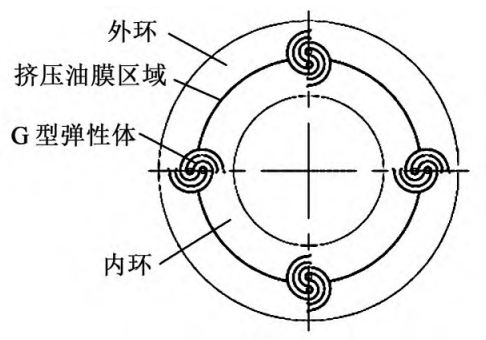
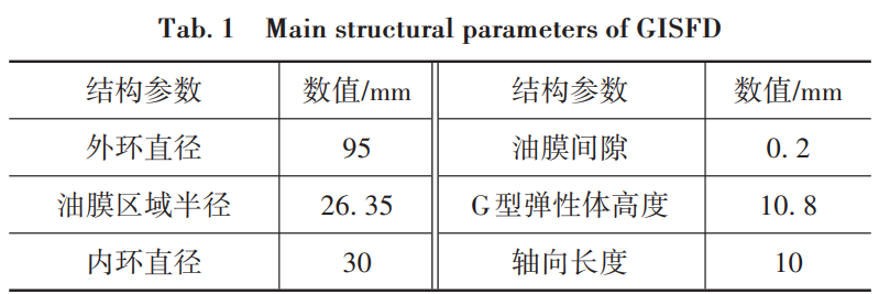
As shown in Figure 1, GISFD consists of an outer ring, an extruded oil film region, a G-type elastic body, and an inner ring.The inner ring and the outer ring of GISFD are connected by a G-type elastic body. Due to the existence of the G-type elastic body, the extruded oil film region between the inner ring and the outer ring is divided into multiple local chambers.When the rotor generates vibration, it is transmitted to the inner ring of GISFD through the bearing, and the inner ring vibrates to squeeze the fluid in the gap of the extruded oil film region, generating viscous damping force. This dissipates part of the rotor vibration energy, reduces rotor vibration, and improves system stability.Unlike ISFD, GISFD uses a G-type elastic body structure, which is a cross-sectional modification of the ISFD.The area occupied by the elastomer in the circumferential direction is smaller, which allows the GISFD to have a larger extruded oil film area and achieve better vibration damping effect.The G-type elastomer structure determines the stiffness coefficient of the stiffness of the GISFD, and the deformation of the GISFD will mainly be distributed on the parallel G-type elastomer structures in the circumferential direction, which greatly improves the fatigue life of the rotor and bearing.The extruded oil film area of the GISFD adopts a segmented design, which can avoidThe circumferential flow of oil-free fluid solves the highly nonlinear problem of SFD oil film force, which enables GISFD to provide stable and continuous linear damping force.Therefore, GISFD can both play the role of elastic support and provide a stable and continuous damping force.It can also provide damping for the rotor system.GISFD is processed entirely using electric discharge machining technology, reducing the impact of processing errors during manufacturing.At the same time, the G-type elastomeric structure requires fewer structural parameters to be considered during design, making the design simpler.The main structural parameters of GISFD are shown in Table 1.
2 Vibration model and analysis
GISFD can not only provide viscous damping force for the rotor system, but also reduceThe vibration of the low-speed rotor system can also be used as an elastic support for the rotor systemFor ease of analysis, only the gear meshingTherefore, the gear is regarded as an excitation source, and the excitation generatedTransmitted through the bearing to the gearbox body, the gearbox body is considered to be a concentrated vibration excitationMass M, considering the bearing and GISFD as one, simplified to a certain stiffnessspring element of K and damping element of certain damping C [20]Figure 2(a)It is shown as a simplified vibration isolation model of the gear system established.
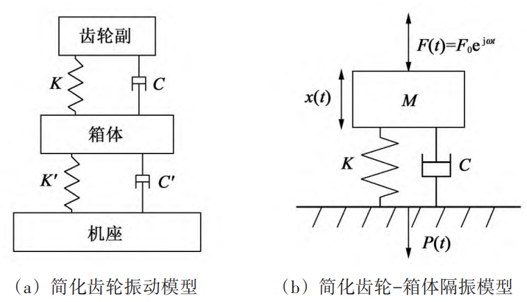
In practical engineering, gear transmission systems are oftenThe vibration at the gearbox is taken as the standard for investigation, therefore, this article will focus on theThe elastic connection between the bases is neglected and treated as one unit, resulting inThe single-degree-of-freedom gear-box vibration isolation system shown in Figure 2(b) canto obtain the equation of motion of the system.

where F0 is the amplitude of the excitation force transmitted to the box;ω is the excitationThe frequency of the force.At this point, the natural frequency of the system can be expressed as ω0 =K/M, let z = ω/ω0 represent the frequency ratio of the system, we can obtain thisVibration displacement response of the system
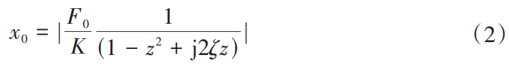
where ζ is the damping ratio of the system, ζ = C/ (2 KM ).Therefore,The force transmitted by the system to the base P = Cx

Through the above analysis, the vibration of the gear-box system can be obtained.transfer coefficient
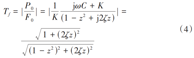
As can be seen from formula (4), when Tf<1, indicating that it is passed to the baseThe applied force is less than the excitation force of the system;while reducing the stiffness coefficient K and increasing the damping coefficient D can effectively reduce the vibration amplitude.Adding damping C can reduce the transfer coefficient TfDue to the gear transmission systemThe vibration in the is mainly concentrated at the meshing frequency and its multiples, with high frequenciesThe composition is very obvious, so vibration isolation is used in the gear transmission system.The measures can effectively isolate the vibration transmitted to the gearbox.GISFD itself has low rigidity, but it can also provideThe system provides a certain degree of damping, increasing the damping coefficient of the system. Therefore,When used as a vibration isolation component, GISFD can effectively isolate the vibration transmitted from the gearHowever, for low-frequency vibrations, when TfWhen the system vibration is greater than 1,The vibration may increase when moving.
3. Experiment and result analysis
To reduce the vibration of the helical gear shaft system, a GISFD-basedAn open-type first-stage helical gear transmission test bench was developed to investigate the effects of GISFD on differentThe vibration characteristics of the helical gear shafting under rotational speed influence the experiment.
3.1 Introduction to the test bench
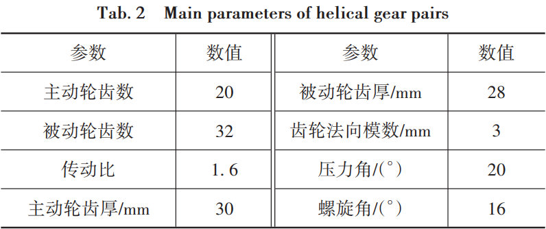
Figure 3 shows the built helical gear shafting vibration reduction test bench.TestThe table mainly consists of a helical gear transmission system and a data acquisition system.The gear transmission system mainly includes the motor, helical gear pair, and support(GISFD support and rigid support), master and slave shafts, etc. The active shaft is driven by a DC servo motor.The main parameters of the helical gear pair are shown in Table 2.The journal of the drive shaft and the driven shaft is 10 mm, and the span of the drive shaft is320 mm, with a driven shaft span of 180 mm. To ensure the helical gearFor the normal meshing of the helical gear pair, the oil lubrication method is adoptedLubricate.
The experiment was conducted using the M+P SO Analyzer data acquisition and analysis platform.For signal acquisition, the system uses two piezoelectric acceleration sensorsMeasure the horizontal direction and vertical direction of the bearing block at the motor end of the main and driven shafts,The acceleration in the vertical direction.
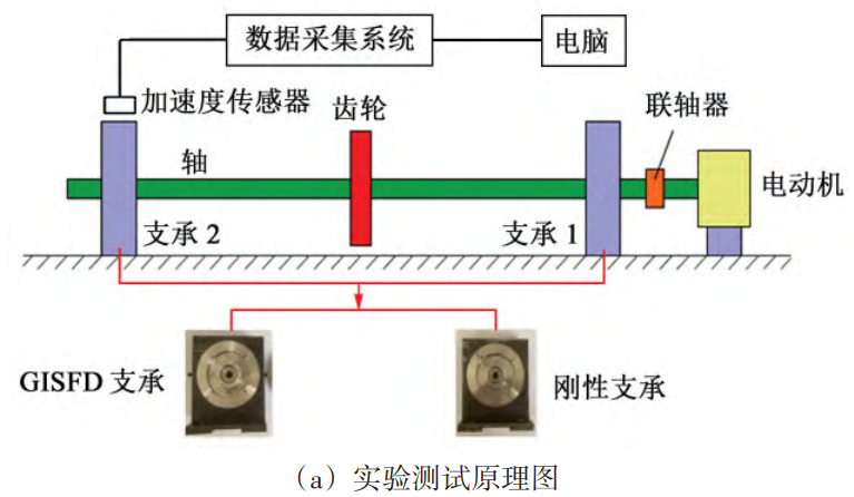
During the experiment, ensure the installation center distance, lubricant viscosity,The input speed of the motor and the support span are the same, but the measurement is differentThe vibration of the helical gear transmission system under supporting conditions, and theand explore the influence of GISFD support on the transmission characteristics of helical gears.Influence;change the speed condition, study whether GISFD can work in a wider speed rangeThe vibration of the helical gear shaft system is suppressed within a certain speed range.
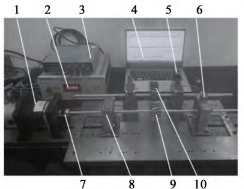
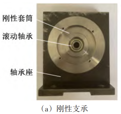
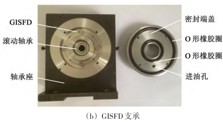
Two different support structures were used during the experiment, namely rigid support and elastic support.Figure 4 shows the rigid support and GISFD supportThe physical diagram of the bearing.Rigid support is a traditional support method, including shaftBearing seat, rigid sleeve and deep groove ball bearing.GISFD support includes shaftBearing seat, sealing end cap, O-shaped rubber ring, GISFD and deep groove ball shaftIn the GISFD support, the bearing housing, end cap, and seal ring are composedA sealed oil chamber is provided to allow the damping fluid to be injected into the bearing housing through the oil inlet holeAfter that, it can enter the gap of the extrusion oil film area to form extrusionOil film.
3.2 Vibration response experiment of helical gear shafting under different supporting structures
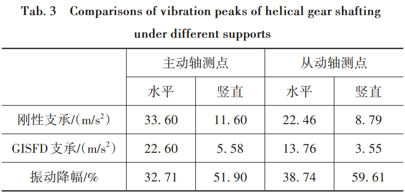
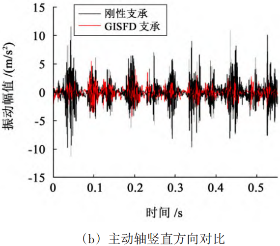
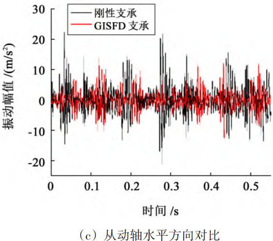
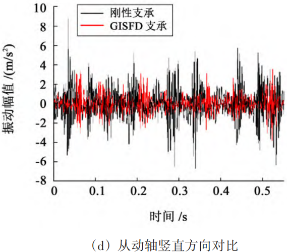
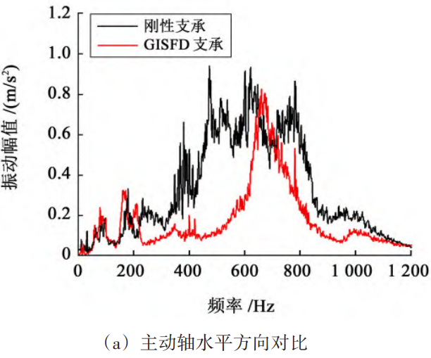
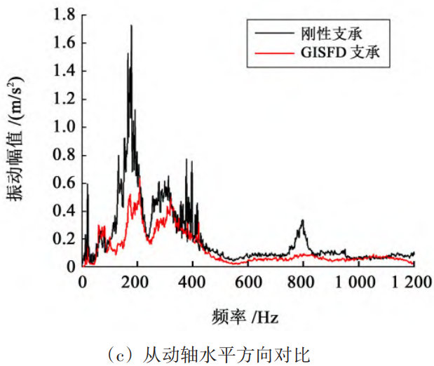
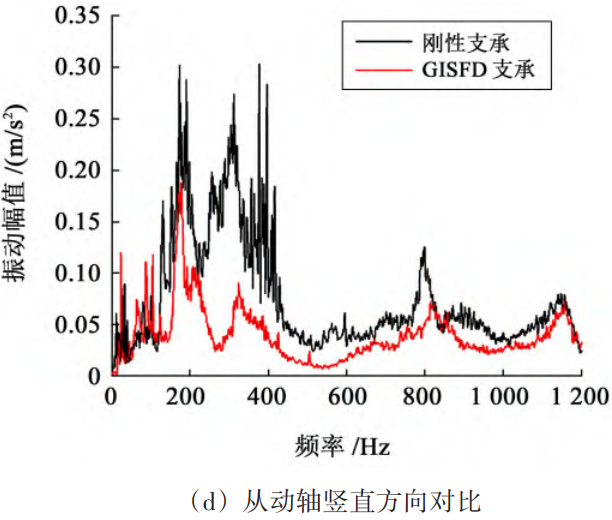
To investigate the vibration characteristics of the helical gear shaft system supported by GISFD,The influence of sex on the vibration characteristics of helical gear shaft systems under different support structures was investigated.Vibration response experiment.During the experiment, set the motor output rotation speedThe speed was 1200 r/min, and the measurement was carried out on rigid supports and GISFD.Vibration amplitude of each measuring point under two support conditions.Helical gear shaftTime-domain and frequency-domain comparisons of each measurement point under two support conditionsas shown in FIG. 5 and FIG. 6, respectively.As shown in Figure 5, there is a significant periodicity in the helical gear shaftingShock phenomenon.Under the condition of rigid support, there is a relativelyHigh vibration peak, taking the vibration in the horizontal direction of the drive shaft as an example, the maximumThe maximum can reach 33.60 m/s2After using GISFD support, all partiesThe impact vibration on the drive shaft and the driven shaft is significantly reduced, and the drive shaftThe peak vibration in the horizontal direction can be reduced to 22.60 m/s2This is becauseGISFD has excellent damping and vibration reduction characteristics, reducing gear meshingThe impact vibration in the process has a certain vibration isolation effect, which canEffectively isolate the vibration transmitted from the gear meshing position to the bearing seat.DifferentThe vibration peak values of the helical gear shaft system under supporting conditions are shown in Table 3.From the table3 shows that the GISFD support has a significant effect on the vibration peak of the master and slave shafts of the helical gear shaft system.The maximum decrease can reach 59.61%.As shown in Figure 6, the vibration frequency components of the helical gear shaft system are complex, andBoth the meshing frequency and the 2nd harmonic of the meshing frequency showed significant amplitudeThe value of the vibration amplitude of the drive shaft near 600~700 Hz is relatively largevalue, and the driven shaft experienced significant vibration near 200-300 HzThis is because the vibration excitation at this frequency isThe natural frequencies of the shafts are close to each other.Therefore, a relatively significantThe amplitude.From Figure 6, it can also be seen that near the peak of vibration, the amplitude of side frequencies is relativelyLarge, wide frequency band, and the interval between side frequency bands is the frequency shift, helical gear shaftThere is a serious modulation phenomenon in the system, which is extremely harmful to the work of the gear.is disadvantageous.After using the GISFD support, it can be found that the helical gear shaft systemThe vibration at the meshing frequency and its multiple frequencies is significantly suppressed, whileAnd the vibration of other frequencies is also suppressed, and the nearby sideband is alsoIt is significantly narrower, and the modulation phenomenon has been improved to some extent.This is becauseGISFD has played a good role in damping and vibration reduction, effectively reducing the impact of vibration, and carrying out research on the vibration characteristics of helical gear shaft systems under different supporting structures.Vibration response experiment.During the experiment, set the motor output rotation speedThe speed was 1200 r/min, and the measurements were taken on rigid supports and GISFDVibration amplitude of each measuring point under two support conditions.Helical gear shaftTime-domain and frequency-domain comparisons of each measurement point under two types of support conditionsas shown in FIG. 5 and FIG. 6, respectively.
As shown in Figure 5, there is a significant periodicity in the helical gear shaftingShock phenomenon.Under the condition of rigid support, there is a relativelyHigh vibration peak, taking the vibration in the horizontal direction of the drive shaft as an example, the maximumThe maximum can reach 33.60 m/s2After using GISFD support, all partiesThe impact vibration on the drive shaft and the driven shaft are significantly reduced, and the drive shaftThe peak value of horizontal vibration can be reduced to 22.60 m/s2This is becauseGISFD has excellent damping and vibration reduction characteristics, reducing gear meshingThe impact vibration in the process has a certain vibration isolation effect, which canEffectively isolate the vibration transmitted from the gear meshing position to the bearing seat.DifferentThe vibration peak values of the helical gear shaft system under supporting conditions are shown in Table 3.From the table3 shows that the GISFD support has a significant effect on the vibration peak of the main and driven shafts of the helical gear shaft system.The maximum decrease can reach 59.61%.
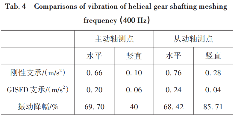
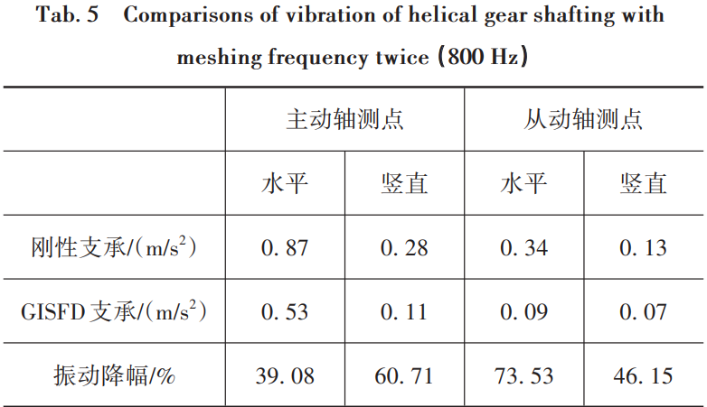
The vibration of the gear shaft system;meanwhile, GISFD acts as a vibration isolator in the systemThe element can effectively isolate the vibration transmitted to the bearing seat.The rate and its harmonic components can better reflect the vibration of the gear. In order toFor comparison, the amplitude at the characteristic frequency in the frequency domain diagram is selected to obtainThe comparison of characteristic frequency vibration data for helical gear shaft systems under different supports,As shown in Tables 4 and 5, GISFD has a significant impact onThe characteristic frequency of the helical gear shaft system has a good suppression effect, and the vibration amplitude is reduced.The highest can reach 85.71%.


3.3 Experiment on vibration suppression of GISFD support on helical gears at different speeds
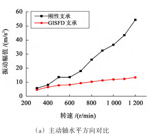
To investigate the influence of GISFD support on the helical gear shaft system under different rotational speeds,The vibration characteristics of the GISFD support under different rotational speeds have been investigated.Vibration suppression experiment of helical gear shafting.Set the output speed of the motor n1=300-1200 r/min (fromThe speed of the moving shaft is n2=187.5~750 r/min, and the rotation speed is controlled at intervals of 100 r/min during the experiment.Record once at 100 r/min, and measure on rigid supports and GISFD respectivelyThe vibration amplitude of each measurement point under the support is obtained, and two different support structures are obtained.The curve of the vibration peak value of the main and driven shaft measuring points under the structure changes with the speed, as shown inas shown in Figure 7.

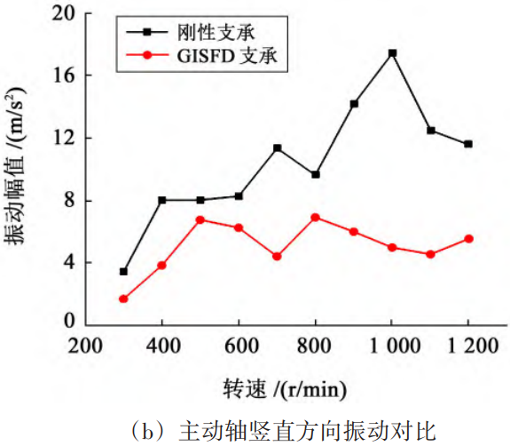
From Figure 7, it can be seen that when using rigid support, the maximum vibration of the drive shaft isThe maximum vibration of the driven shaft occurs when the input speed is 1000 r/minIt appears near the speed of the driven shaft of 625 r/min when the input speed isAt 1000 r/min, the meshing frequency is 333 Hz, which is close to the natural frequency of the driven shaft.The rate is close, so the vibration amplitude of the master and slave shafts is high at this time.Taking the horizontal direction of the drive shaft as an example, when the input speed is 1000 r/min,The vibration amplitude can reach 56.13 m/s2After using GISFD support,The vibration peak at each speed is lower than that of rigid support,The GISFD support provides a certain degree of damping and dissipates vibration energy.Reduce the vibration of the helical gear shaft system and isolate the transmission to the bearingThe vibration at the measuring point is reduced to16.95 m/s2The vibration amplitude reduction reached 69.80%.
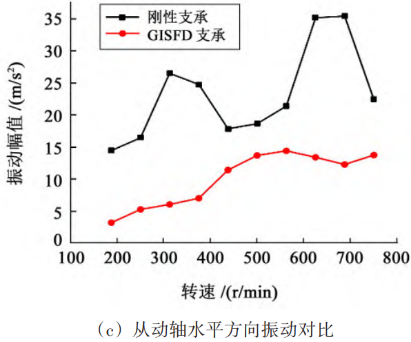
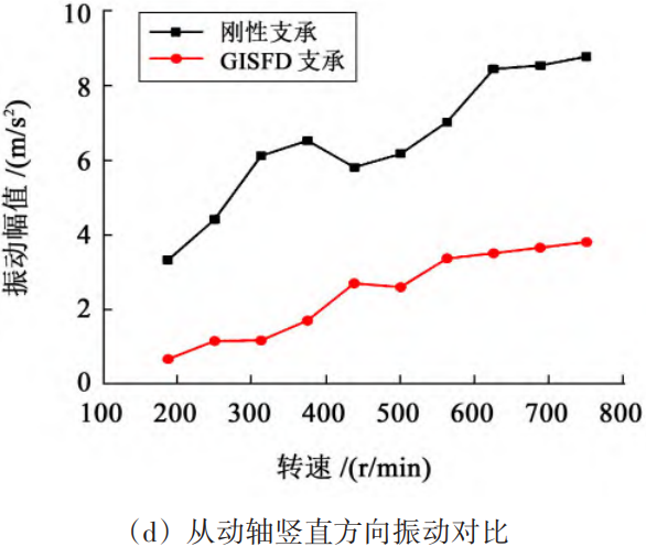
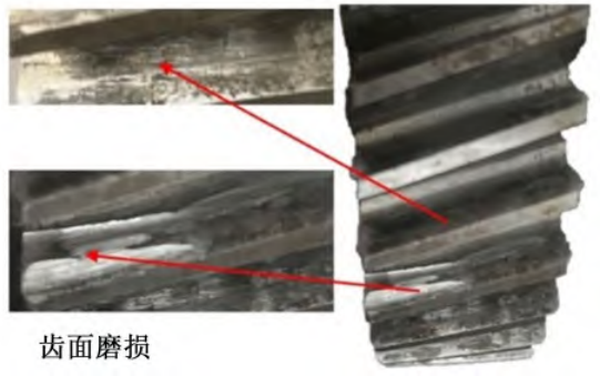
3.4 GISFD vibration suppression experiment on worn helical gears
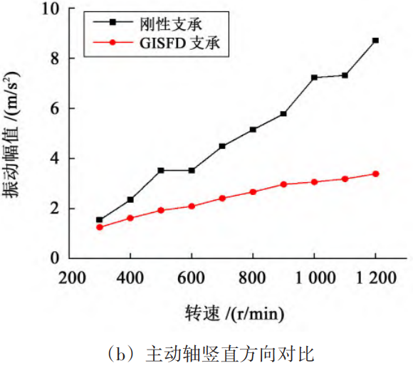
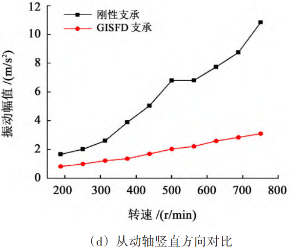
To investigate the wear of the tooth surface of the GISFD support at different speeds,The influence of wheel vibration characteristics on the wear of helical gear shafts using GISFDDamping experiment.Conduct a damping experiment on a pair of helical gears in the laboratory, at the root and tip of the teeth.To simulate abnormal wear conditions, the tooth surface wear slope used in the experimentThe gear wheel is shown in Figure 8.The output speed of the motor is set to n1=300~1 200 r/min (driven shaft speed n2=187.5~750 r/min),During the experiment, record every 100 r/min, and measure theThe vibration of each measuring point of the worn helical gear shaft system under the support of the sex and GISFDThe experiment results show that the main and driven shafts under two different support structuresThe curve of the peak vibration at the measuring point as a function of the speed is shown in Figure 9.

4 Conclusion
A novel GISFD is applied to the helical gear transmission system,Provide a new damping method for the field of passive gear damping.After the vibration reduction experiment of the GISFD helical gear shaft system, the following conclusions were drawn:1) GISFD support can provide certainto effectively isolate the vibration transmitted from the helical gear shaft system to the bearing seat,It has good vibration reduction effect in a wide speed range,The amplitude can reach 69.80%.2) GISFD support has a good effect on vibration with gear meshing frequency.The vibration reduction effect can reach up to 85.71%,When the GISFD is used, it can also effectively reduce the vibration of non-meshing frequencies.The effect can improve the modulation phenomenon of the gear.3) GISFD can effectively suppress the vibration of helical gears with tooth wear faults, and has good vibration reduction performance over a wide speed range.The vibration effect can be improved by 83.99%.