
The gear tooth root dynamic strain measurement experiment is carried out on an industrial standard gearbox, which is installed on an electric closed transmission test bench. The whole test bench is shown in Figure 1. The gearbox test bench consists of two 45KW Siemens Servo Motors. Motor 1 is connected with the driving gear as the driving motor; motor 2 is connected with the driven gear as the load motor. Compared with the traditional open-loop test-bed, the electric closed-loop test-bed is economical and efficient, and can match almost any load and speed within the rated power range. The gearbox used in the experiment is a first-order reduction gearbox. The driving gear has 40 teeth and the driven gear has 72 teeth. Therefore, the transmission ratio of the gearbox is 1.8:1.
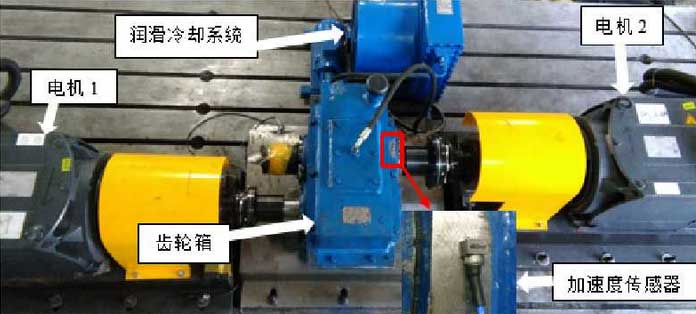
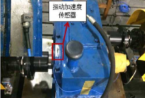
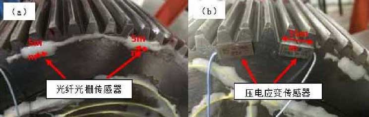
In the experiment, a three-axis vibration acceleration sensor is installed on the gearbox, and a light grating sensor and a piezoelectric strain sensor are installed on the end face of the driven gear. The three-axis vibration acceleration sensor is installed on the upper gear box of the bearing block near the output end of the driven gear to monitor the vibration condition of the gearbox. The installation position of the vibration acceleration sensor is shown in Fig. 2. A total of 9 light grating sensors are roughly installed on the tooth root circle of the driven gear end face, and the dynamic bending strain of the gear tooth root is measured by using the light grating sensor. The fiber Bragg grating sensor for measuring gear root strain has a grating length of 5 mm and a spacing of 58 mm for each fiber. In order to cross verify and compare the tooth root strain, two piezoelectric strain sensors produced by PCB company are also fixed on the tooth root of gear end face where fiber Bragg grating sensor is installed. The resolution of piezoelectric strain sensor is 0.0006 micro strain, and the frequency response range is 100 kHz.
In the experiment of gear tooth root dynamic strain measurement, fiber Bragg grating strain signal and piezoelectric strain signal are collected by rotating collimator and slip ring brush respectively. The distribution of FBG sensor and piezoelectric strain sensor is shown in Fig. 3. In the experimental signal acquisition, the sampling rate of FBG sensor is set at 5000Hz, while the sampling rate of vibration acceleration sensor and piezoelectric strain sensor is set at 20.48khz.
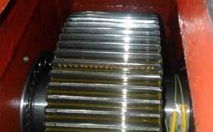
In the experiment of gear root dynamic strain measurement, there are two kinds of gear systems: healthy gear and moderate pitting fault gear. The pitting fault is artificially made on a tooth of the driven gear. A moderate degree of pitting fault is produced on a tooth surface of the driven gear by using an electric spark machine. The depth of the pitting corrosion on the tooth surface is about 0.5mm, and the diameter of the pitting corrosion is 3mm. There are 19 pitting corrosion with the same degree distributed along the tooth width direction. Tooth surface pitting failure is shown in Fig. 4.
Within the rated power range of gearbox test bench, the minimum speed of gearbox input shaft is 100RPM and the maximum speed is 3600rpm; the minimum torque and maximum torque of gearbox output shaft are 50nm and 500nm respectively. At the same time, the acceleration sensor, fiber Bragg grating sensor and piezoelectric strain sensor are used to collect signals. Five groups of data are collected under each operating condition. In different gear states, i.e. healthy gear and moderately pitting fault gear, the above experimental process is repeated.