All kinds of helical gear shafts are components that transmit motion and power, and are used in many mechanical or transmission equipment. At present, the machining of spiral gear shaft is basically completed by the methods of material removal, such as CNC turning and whirlwind milling, which not only has low efficiency, but also has low material utilization. Rolling can be used to roll the thread, the process is generally cold forming, rolling out the thread wall thickness and tooth height is small, the tooth shape accuracy of the thread is low, generally only used to fasten parts. Cross wedge rolling is an advanced rolling process with high efficiency and cleanness. The technology of cross wedge rolling is becoming more and more mature, which is suitable for processing step shaft and shaft with complex profile . The technology of cross wedge rolling step shaft has been very mature, and there is a solid theoretical basis for rolling special shaft parts such as camshaft, which provides a theoretical basis for cross wedge rolling of spiral teeth. At present, the part rolling center of Beijing University of science and technology has carried out a detailed study on the technology of cross rolling screw shaft, and obtained the conclusions of die design method and forming law. ZHY gear studies the rolling technology of cross wedge rolling of spiral gear shaft, and obtains the influence rule of some process parameters on the forming through the finite element simulation, but it has not been verified by the experiment. According to the forming characteristics of trapezoidal spiral gear, ZHY gear designed the experimental die and carried out the rolling experiment of trapezoidal spiral gear shaft by cross wedge rolling, and obtained the influence rule of billet and die helix angle on trapezoidal spiral gear by cross wedge rolling.
1. Experiment description
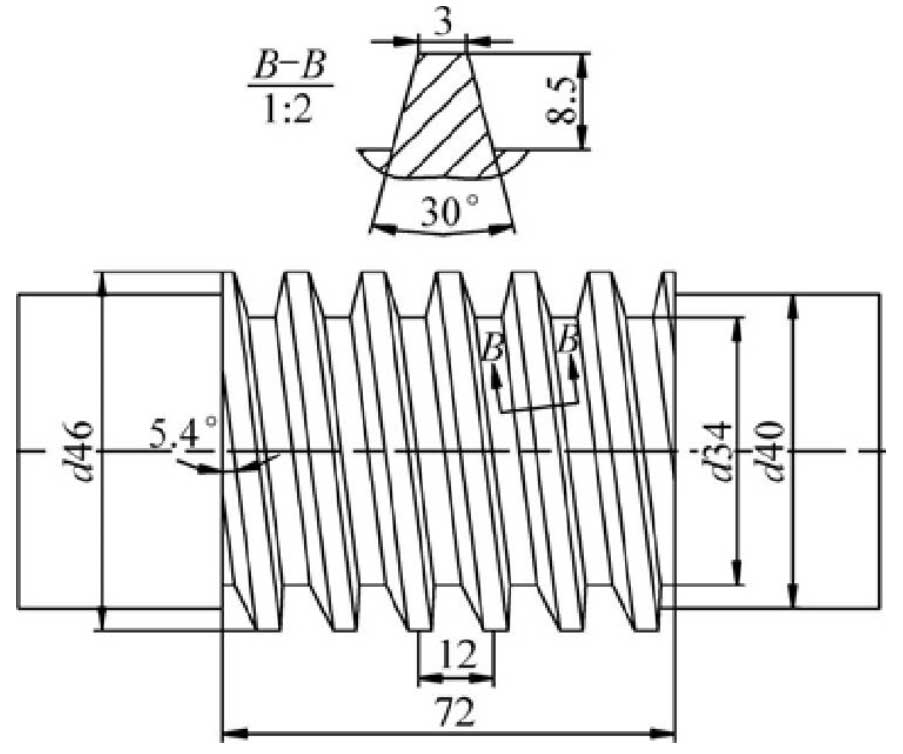
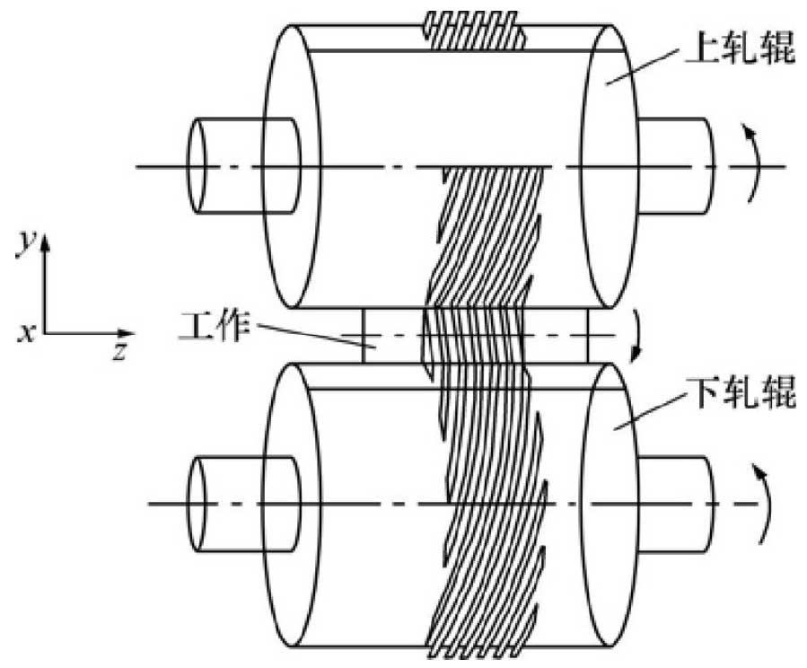
In H630 cross wedge rolling mill, the profile section of the spiral shaft is trapezoid, and the blank size of the rolled piece is shown in Figure 1. According to the helix angle of billet and die, a series of rolling experiments are arranged. The rolling temperature is 1200 ℃, the minimum distance between upper and lower dies is 42 mm, and the rolling speed is 9 R / min. the rolling model is shown in Figure 2. Taking the helix angle of billet and die as the research parameters, the influence of technological parameters on the helix axis of cross wedge rolling is analyzed from the aspects of tooth height, pitch and whether there is helix mark on the tooth segment.
2. Die design with different helix angle
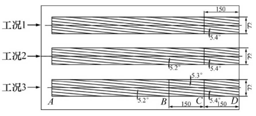
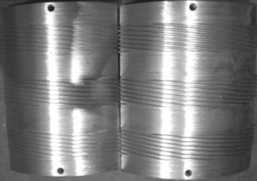
The pass of cross wedge rolling die is a spatial structure. The die cavity is designed according to the theory of constant metal volume in the forming process. Figure 3 shows the schematic diagram of die development. There are three sets of dies arranged on the die surface, i.e. working conditions 1, 2 and 3. The length and width of the dies are equal, among which AC is the tooth forming section and CD is the finishing section. The helix angle of forming section is different in three working conditions. The helix angle of forming section in working conditions 1 and 2 is 5.4 ° and 5.2 ° respectively. The helix angle of forming section in working condition 3 is divided into two sections, namely 5.2 ° and 5.3 °. The final experimental die is shown in Figure 4. Rolling experiments were carried out under three working conditions, and the influence of helix angle on tooth profile was obtained.
3. Rolled stock
The blank is made of 45 steel. In order to analyze the influence of the size and shape of the blank on the forming of the rolled piece, the experimental blank is designed into two types: round blank and concave cone blank. Yan Huajun et al. Calculated the initial tooth height of the die by the space integral method according to the theory of equal volume of screw tooth profile pressing and extruding. The diameter expression of the following round billet was obtained by finishing the method:

Where: γ is the helix angle; R1 and R2 are the tooth top radius and tooth bottom radius of the rolled piece; a and B are the upper and lower bottom lengths of the cross section tooth profile in Figure 1; h is the height of the tooth profile.
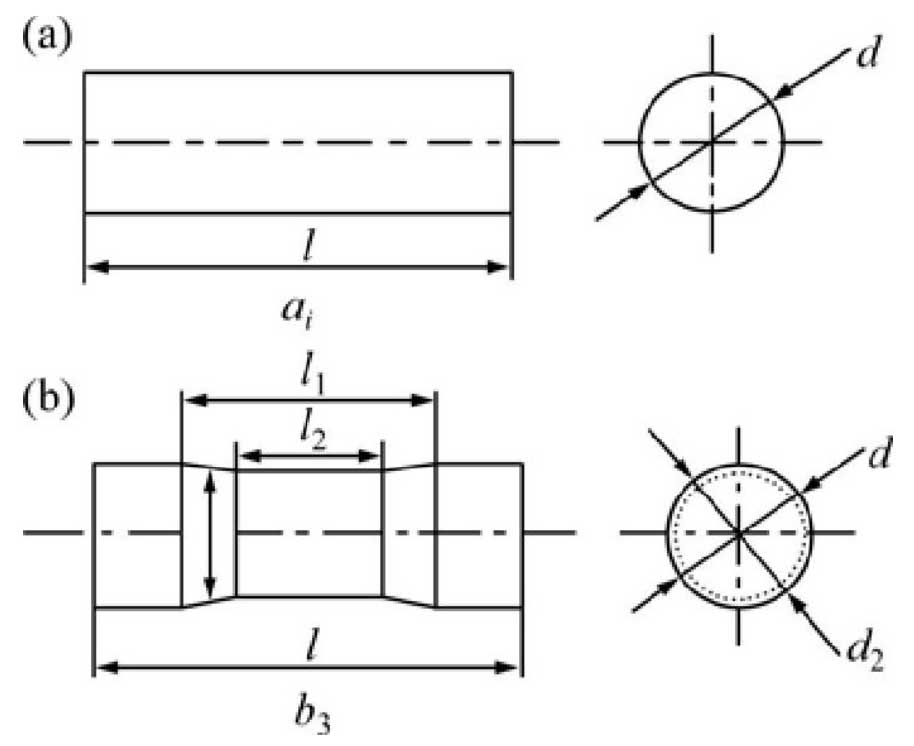
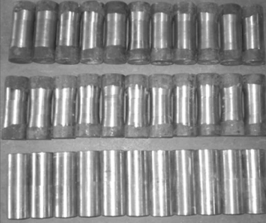
According to formula (1), the billet diameter is 40 mm. In the experiment, the billets are grouped according to the shape and size in the annotation form given in Fig. 5, and the data is shown in Table 1. Prepare 3 pieces of each kind of billets, and part of the experimental billets obtained are shown in Fig. 6.
