1. Introduction
Bevel gears play a crucial role in various mechanical systems, especially in the automotive industry, where they are used in the main reducer to control the vehicle’s steering, adjust the linear speed of the inner and outer wheels, and ensure smooth turning. However, the abnormal fracture of bevel gears before the normal service life not only affects the performance and safety of the vehicle but also causes economic losses. Therefore, it is of great significance to conduct a comprehensive failure analysis and propose effective improvement measures. This article focuses on the failure analysis of an active bevel gear in a car’s main reducer, aiming to provide a theoretical basis for improving the quality of bevel gears and optimizing the manufacturing process.
2. Role and Manufacturing Process of Bevel Gears
2.1 Function in the Automotive Transmission System
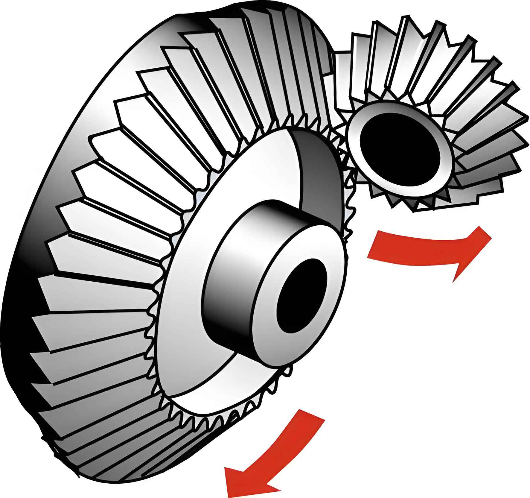
The main reducer in the automotive transmission system is responsible for reducing the speed, increasing the torque, and changing the direction of the torque rotation. It consists of one or more pairs of reduction gear pairs. The bevel gear, particularly the active bevel gear, is a key component in this system. It inputs power and transmits it to the driven gear, enabling the control of the vehicle’s steering system. By adjusting the rotational speed and torque distribution between the inner and outer wheels during turning, the bevel gear ensures that the vehicle can turn smoothly and safely.
2.2 Manufacturing Process
The manufacturing process of bevel gears typically involves several steps: blanking, hot forging, normalizing (pre – heat treatment), rough machining, finish machining, carburizing and quenching, tempering, and precision grinding. Pre – heat treatment, such as normalizing, is essential as it can eliminate the non – uniform distribution of austenite, relieve the stress generated during forging, reduce the risk of crack formation, improve the machinability, and prepare for the final quenching and tempering heat treatment.
3. Failure Analysis of Bevel Gears
3.1 Macroscopic Observation
In this study, the active bevel gear under investigation showed that most of the gear teeth had fractured, and macroscopic cracks had also appeared at the roots of the unfractured gear teeth. By observing the fracture surface, distinct beach – mark – like crack propagation traces were found on two of the broken teeth, indicating low – cycle fatigue fracture. The physical appearance of the broken gear is shown in Figure 1. [Insert Figure 1: Broken gear here]
3.2 Chemical Composition Analysis
The chemical composition of the gear tooth surface was measured using a direct – reading spectrometer. The gear was made of 20CrMnTiH steel, and the analysis results are presented in Table 1. All the elements met the requirements specified in GB/T3077 – 2015 “Alloy Structural Steel Standard”.
| Element | Content (%) |
|---|---|
| C | 0.22 |
| Si | 0.33 |
| Mn | 0.65 |
| P | 0.015 |
| S | 0.016 |
| Cr | 1.06 |
| Ti | 0.056 – 0.058 |
| Cu | 0.029 |
| Ni | – |
3.3 Hardness Test
Samples were taken from the remaining tooth surface and the matrix interior, and the Rockwell hardness of each part was measured. The test results are shown in Table 2. The matrix hardness values were close to the lower limit of the design requirements. The average surface hardness of the gear was lower than the design value, and there was significant hardness non – uniformity, with a large numerical gradient in surface hardness. This indicated the presence of abnormal structures in the surface layer.
| Test Item | Hardness Value 1 (HRC) | Hardness Value 2 (HRC) | Hardness Value 4 (HRC) | Average Hardness (HRC) |
|---|---|---|---|---|
| Surface | 53.3 | 58.9 | 54.1 | 56.4 |
| Matrix | 32.7 | 32.3 | 32.1 | 32.6 |
3.4 Determination of the Effective Carburized Hardened Layer Depth
Samples were taken at three points on the surface layer, and the average effective carburized hardened layer depth of the gear was measured using a micro – Vickers hardness tester. The measured value was 0.86mm, which was within the design range of 0.8 – 1.1mm, with a hardness limit of 550HV1. According to the standard (GB/T9450 – 2005 “Determination and Verification of the Hardened Layer Depth of Carburized and Quenched Steel Parts”), the measurement result met the design requirements.
3.5 Metallographic Analysis
Metallographic specimens were prepared from the broken teeth. After rough grinding, fine grinding, and polishing, non – metallic inclusions were observed under a metallographic microscope. Only a small number of spherical oxides, all below grade 1, were found near the fracture and in the matrix, as shown in Figure 2. Therefore, non – metallic inclusions were not the main cause of gear fracture. [Insert Figure 2: Spherical oxide here]
After etching the polished specimens with 4% nitric acid alcohol, washing, and drying, the microstructure of the carburized hardened layer on the surface of the unfractured gear was observed. It consisted of fine – needle – like martensite and a small amount of retained austenite, which was a normal product after quenching, as shown in Figure 3. The microstructure of the core was lath – like bainite and sorbite. Although this core microstructure could reduce the bending strength of the gear, it was located in the core area, which was not the main stress – bearing part, so its impact on gear fracture was relatively small. [Insert Figure 3: Surface microstructure here] [Insert Figure 4: Matrix microstructure here]
However, a network – like non – martensitic structure was found on the surface of the broken gear root, with a measured depth of approximately 0.04mm, as shown in Figure 5. In an ideal situation, the surface of the carburized (or carbonitrided) and quenched parts should have a fine – needle – like high – carbon martensite structure. But due to various uncontrollable factors in the heat treatment and processing processes, a mixed non – martensitic structure such as bainite and troostite (pearlite – like) was formed on the gear surface, resulting in serious quality defects. According to the national automotive industry standard QC/T262 – 1999 “Metallographic Inspection of Carburized Gears for Automobiles”, the maximum depth of non – martensitic structure on the gear surface should not exceed 0.02mm. In this case, the non – martensitic structure depth of the gear was 0.04mm, and it penetrated along the original austenite grain boundary in a network – like pattern. Such a deep non – martensitic structure significantly reduced the surface hardness, wear resistance, and fatigue limit of the gear. It also initiated micro – cracks from the stress – concentration areas at the grain boundaries or oxides, forming crack sources, which ultimately led to gear fracture during subsequent service due to insufficient bending strength. [Insert Figure 5: Superficial non – equine microstructure here]
4. Discussion of Test Results
The presence of a deep non – martensitic structure on the gear surface, which penetrated along the original austenite grain boundary in a network – like pattern, was the main cause of gear failure. This structure severely weakened the surface and grain – boundary strength of the gear, reduced its wear resistance and fatigue life. The non – uniform surface hardness caused by the non – martensitic structure led to stress concentration during gear operation, generating fatigue crack sources. The continuous expansion of multiple crack sources eventually led to gear fracture, significantly shortening the gear’s fatigue life.
5. Improvement Measures and Effects
5.1 Root – Cause Solutions
There are two main ways to address the problem of non – martensitic structure formation. One is to select materials with fewer elements that are preferentially oxidized. The order of preferential oxidation of different elements is \(C>Ce>Ba>Mg>Al>Ti>Si>B>V>Nb>Mn>Cr>Cd>Fe>P>Mo>Sn>Ni>As>Cu\). The other is to reduce the oxidizing components in the carburizing atmosphere, such as lowering the oxygen partial pressure. In the context of domestic gear production, the second method is more acceptable to manufacturers.
5.2 Specific Improvement Measures
- Enhance the Purity of the Carburizing Atmosphere: The formation of non – martensitic structure indicates the presence of an oxidizing atmosphere in the heat treatment furnace. Therefore, it is necessary to improve the cleanliness of the carburizing atmosphere in the furnace. This can be achieved by strictly controlling the furnace’s sealing performance and appropriately extending the exhaust time to make the carburizing atmosphere in the furnace purer.
- Improve Surface Hardness: Since the overall surface hardness of the failed gear was low, appropriately increasing the surface hardness can improve the tooth – surface contact fatigue strength. This can be achieved by ensuring the cleanliness of the workpiece surface before carburizing, which helps to increase the surface hardness and its uniformity.
- Adjust the Quenching Cooling Rate: During the carburizing process, the carbon potential at the gear root is relatively high, and the cooling rate is slower than that of other parts, making it prone to the formation of non – martensitic structure. Therefore, it is necessary to appropriately increase the quenching cooling rate of the gear to reduce or eliminate this defect.
5.3 Effect Verification
After adjusting the heat treatment process according to the improvement suggestions (including the control of the oxidizing atmosphere and the quenching cooling process), a new batch of gears was sampled and observed. No obvious network – like surface non – martensitic structure was found. Although completely eliminating this structure requires high – quality materials and precise heat treatment processes, the process adjustment significantly improved the surface structure defects of the gears. This indicates that the analysis method proposed in this article is highly effective and can provide valuable guidance for the gear treatment process.
6. Conclusion
In this article, a comprehensive failure analysis of an abnormal – fractured active bevel gear was carried out through macroscopic observation, chemical composition analysis, hardness testing, determination of the effective carburized hardened layer depth, and metallographic analysis. The results showed that the deep non – martensitic structure on the gear surface was the main cause of gear failure. Based on this, corresponding improvement measures were proposed, and after implementing these measures, the surface structure of the new batch of gears was significantly improved. This study provides a reference for the failure analysis and improvement of bevel gears in the future, helping to improve the quality and reliability of bevel gears and promoting the development of the gear manufacturing industry.