This paper focuses on the recurring bearing cage fracture failures in the 16# and 17# rolling mill gearboxes at a special steel high – speed wire rod mill. Through a series of on – site inspections, vibration monitoring data analysis, and material changes, the root causes of the failures are explored, and effective solutions are proposed. The results show that the current vibration monitoring system has limitations in predicting bearing cage fractures, and replacing the bearing cage material can significantly improve the reliability of the equipment.
1. Introduction
In the production process of special steel high – speed wire rod mills, the normal operation of rolling mill gearbox bearings is crucial for the stable production of the entire production line. However, in a certain special steel high – speed wire rod mill, the 16# and 17# rolling mill gearbox distribution shaft radial bearings have experienced three cage fracture failures, which have seriously affected the production efficiency and product quality of the mill.
The first bearing cage fracture failure occurred on April 13, 2024. After that, technical personnel installed vibration sensors in the gearbox for monitoring. But in the subsequent two bearing cage fracture accidents, the online vibration monitoring sensors failed to pick up the abnormal vibration signals caused by the bearing cage fractures 24 hours in advance. This situation has attracted great attention from the plant’s technical department, and a series of in – depth investigations and analyses have been carried out.
2. Equipment Transmission and Monitoring Point Layout
2.1 Equipment Composition
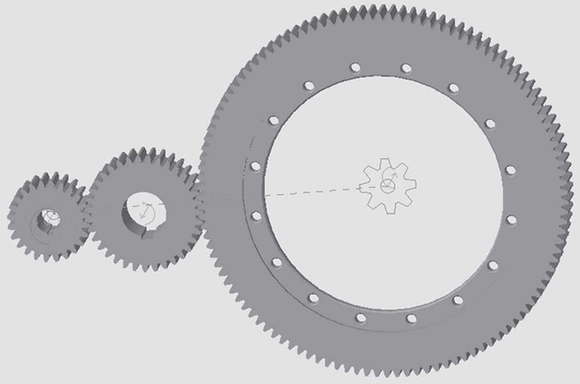
The 16# and 17# rolling mills are mainly composed of motors, gearboxes, and roll boxes. The motor has a power of 1500 kW. The structure of the motor and gearbox is shown in Figure 1.
| Component | Function |
|---|---|
| Motor | Provide power for the rolling mill |
| Gearbox | Transmit and adjust the power and speed |
| Roll box | Shape the steel wire rod |
2.2 Monitoring Point Layout Evolution
After the first bearing fracture failure, only the axial measuring points of the gearbox input shaft and the measuring points of the 16# and 17# roll box casings were used for vibration monitoring. The layout of these measuring points was mainly due to the limitations of the installation position of the 16# and 17# distribution shaft bearings. The vibration monitoring at this stage was relatively simple and could not comprehensively reflect the operating status of the key bearing components.
After the second bearing fracture failure, in order to improve the accuracy of vibration monitoring, new vibration sensors were added, and the layout of the sensor positions was optimized. The optimized vibration monitoring point layout is shown in Figure 3.
| Monitoring Point | Location | Significance |
|---|---|---|
| Input shaft drive – end axial | At the drive – end of the input shaft | Monitor the axial vibration of the input shaft drive – end |
| Input shaft free – end axial | At the free – end of the input shaft | Monitor the axial vibration of the input shaft free – end |
| 16# distribution shaft drive – side near – bearing rib plate horizontal | On the horizontal side of the rib plate near the bearing on the drive – side of the 16# distribution shaft | Monitor the vibration of the 16# distribution shaft drive – side |
| 16# distribution shaft free – end axial | At the free – end of the 16# distribution shaft | Monitor the axial vibration of the 16# distribution shaft free – end |
| 17# distribution shaft drive – side axial | At the drive – side of the 17# distribution shaft | Monitor the axial vibration of the 17# distribution shaft drive – side |
| 17# distribution shaft free – end near – bearing rib plate vertical and axial | At the vertical and axial positions of the rib plate near the bearing on the free – end of the 17# distribution shaft | Monitor the vibration of the 17# distribution shaft free – end |
3. Gearbox Bearing Vibration Analysis
3.1 Vibration Characteristics After the First Bearing Replacement
After replacing the bearings in the gearbox on April 17, 2024, the vibration acceleration waveform showed impact signals with the rotation frequency of the 16# and 17# distribution shafts. The vibration acceleration value was \(2.3m/s^2\), and there were also equally – spaced impact signals in the frequency spectrum. This indicates that after the bearing replacement, the rotation of the shaft is unstable, which may be due to excessive bearing clearance. Although the vibration amplitude is small, it still reflects potential problems in the bearing operation. The vibration acceleration waveform and frequency spectrum monitoring data of the gearbox input shaft on April 20, 2024 are shown in Figure 4 and Figure 5.
| Date | Vibration Acceleration Waveform Feature | Vibration Acceleration Value | Frequency Spectrum Feature |
|---|---|---|---|
| April 20, 2024 | Impact signals with the rotation frequency of the 16# and 17# distribution shafts | \(2.3m/s^2\) | Equally – spaced impact signals |
3.2 Vibration Status Before the Second Bearing Failure
On May 26, 2024, before the 17# distribution shaft bearing failure, the trends of the speed and acceleration values at the axial measuring point of the gearbox input shaft were stable, and the vibration amplitudes were small. The vibration speed amplitude was within \(0.6mm/s\) (as shown in Figure 6), and the acceleration amplitude was within \(3m/s^2\) (as shown in Figure 7). There was no obvious upward trend in the vibration value.
| Date | Vibration Speed Amplitude | Vibration Acceleration Amplitude | Vibration Value Trend |
|---|---|---|---|
| May 26, 2024 | Within \(0.6mm/s\) | Within \(3m/s^2\) | Stable, no obvious upward trend |
In the vibration monitoring frequency spectrum on May 26, 2024, there was an equally – spaced impact signal with a frequency of \(28.125Hz\) (as shown in Figure 8). In the envelope demodulation spectrum of the axial vibration acceleration frequency spectrum of the gearbox input shaft (as shown in Figure 9), impact frequencies equal to the rotation frequency (\(28.125Hz\)) of the 17# distribution shaft and its second, third, and fourth harmonics appeared, but there were no obvious abnormal signals.
| Date | Impact Signal Frequency in Frequency Spectrum | Impact Frequencies in Envelope Demodulation Spectrum | Abnormal Signal Status |
|---|---|---|---|
| May 26, 2024 | \(28.125Hz\) | Rotation frequency of 17# distribution shaft (\(28.125Hz\)) and its second, third, and fourth harmonics | No obvious abnormal signals |
3.3 Vibration Changes After Adding Monitoring Points
After adding 7 vibration sensors to the gearbox for monitoring on the afternoon of May 28, 2024, according to the vibration data monitored on May 30 and 31, the gearbox had impact signals of the 16# and 17# distribution shafts, and the impact signal characteristics were obvious (as shown in Figure 10). The operation of the 16# and 17# distribution shafts was unstable. In the envelope demodulation spectrum, impact frequencies equal to the rotation frequency (\(28.438Hz\)) of the 17# distribution shaft and its second, third, and fourth harmonics appeared (as shown in Figure 11). This indicates that the vibration monitoring after adding sensors can better reflect the unstable operation state of the distribution shafts, but it still cannot effectively predict the bearing cage fracture failure in advance.
| Date | Vibration Signal Feature | Distribution Shaft Operation Status | Impact Frequencies in Envelope Demodulation Spectrum |
|---|---|---|---|
| May 30 – 31, 2024 | Obvious impact signals of 16# and 17# distribution shafts | Unstable | Rotation frequency of 17# distribution shaft (\(28.438Hz\)) and its second, third, and fourth harmonics |
3.4 Vibration Situation Before the Third Bearing Failure
On June 27, 2024, when the 16# and 17# rolling mill gearboxes made abnormal noises again, it was found that the bearing cage of the 17# distribution shaft in the gearbox had fractured for the third time. The vibration speed value at the axial measuring point of the free – end of the 17# distribution shaft was small (as shown in Figure 12), and the acceleration value was also small, but there was a slight increase trend (as shown in Figure 13). The vibration speed value at the axial measuring point of the free – end of the input shaft was small (as shown in Figure 14), and the acceleration value had an increasing trend with a large amplitude (as shown in Figure 15). However, there were no obvious abnormal signals in the vibration waveform and frequency spectrum (as shown in Figure 16 and Figure 17).
| Measuring Point | Vibration Speed Value | Vibration Acceleration Value | Vibration Waveform and Frequency Spectrum Feature |
|---|---|---|---|
| 17# distribution shaft free – end axial | Small | Small, with a slight increase trend | No obvious abnormal signals |
| Input shaft free – end axial | Small | Large amplitude, increasing trend | N |
4. Reasons for the Failure of Vibration Monitoring in Predicting Bearing Cage Fractures
4.1 Characteristics of Bearing Cage Fracture Failures
Bearing cage fracture failures are different from failures of bearing inner rings, outer rings, and rolling elements. Failures of inner rings, outer rings, and rolling elements usually take a certain amount of time to form. During this process, the vibration value of the bearing will increase gradually, and obvious fault characteristic frequencies of bearing components will appear in the vibration waveform and frequency spectrum signals, making it easier to identify the failures.
However, the fault characteristic frequency of the bearing cage is the smallest among all bearing component fault frequencies, which makes it difficult to identify. Once the bearing cage fractures, it is already in the late stage of the bearing failure. The fracture occurs instantaneously and is generated in a very short time. After the failure, the change in the vibration value is not obvious, so it is difficult to predict through vibration monitoring.
4.2 Limitations of the Vibration Monitoring System
Although vibration sensors were installed in the gearbox for monitoring, due to the limitations of the installation position, the sensors could not be installed near the key bearing parts that were of most concern. In the first – stage monitoring, only the axial measuring points of the gearbox input shaft and the measuring points of the 16# and 17# roll box casings were used for monitoring, which could not directly obtain the vibration information of the bearings. Even after optimizing the sensor layout in the second – stage monitoring, the monitoring effect was still limited, and it was difficult to accurately predict the bearing cage fracture failures.
5. Solutions and Effects
5.1 Material Replacement of the Bearing Cage
In early July 2024, through in – depth analysis, the material of the bearing cage of the 17# distribution shaft bearing in the gearbox was re – selected. The original steel – made bearing cage was replaced with a copper – made bearing cage with better plasticity and ductility. After the replacement, the new bearing has been operating normally for four months as of November 3, 2024. This shows that changing the material of the bearing cage can effectively improve the reliability of the bearing and avoid the recurrence of bearing cage fracture failures.
5.2 Comparison of Different Bearing Cage Materials
| Bearing Cage Material | Plasticity | Ductility | Resistance to Fracture | Application Effect in This Case |
|---|---|---|---|---|
| Steel | Relatively poor | Relatively poor | Relatively low | Prone to cage fracture failures |
| Copper | Stronger | Stronger | Higher | No cage fracture failures in four months of operation |
6. Conclusion
The recurring bearing cage fracture failures in the 16# and 17# rolling mill gearboxes of the special steel high – speed wire rod mill have been a major problem affecting production. Through the analysis of vibration monitoring data and the exploration of failure reasons, it is found that the current vibration monitoring system has limitations in predicting bearing cage fractures, mainly due to the instantaneous nature of bearing cage fracture failures and the limitations of the vibration monitoring system itself.
Replacing the bearing cage material from steel to copper with better plasticity and ductility is an effective measure to solve the problem of bearing cage fracture failures. This measure can improve the reliability of the bearing and ensure the stable operation of the rolling mill gearbox. In future production, continuous improvement of the vibration monitoring system, such as optimizing sensor layout and improving signal processing algorithms, and regular inspection and maintenance of bearings are still necessary to prevent potential bearing failures and ensure the normal operation of the production line.