
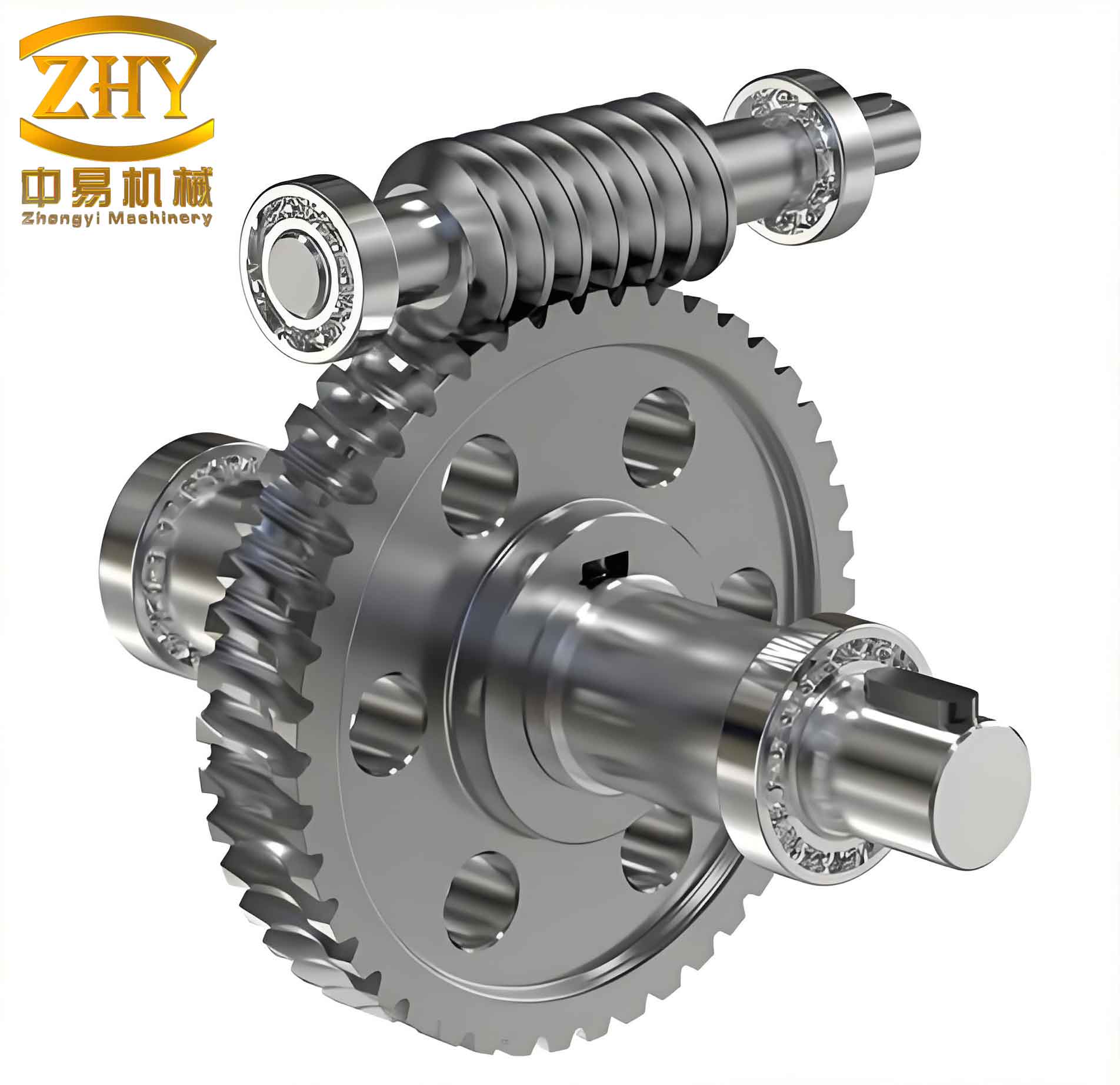
In my practice as a mechanical failure analyst, I encountered a rare but critical failure mode in a worm gear lifting mechanism: the worm shaft experienced severe bending deformation after the worm gear set became glued and seized. This mechanism was designed to lift heavy fermentation tanks between two floors in a bio-processing plant. The system consisted of three SWL-25 type worm gear units arranged in a line on a platform. Each worm shaft connected at its bottom to a steel beam lifting carriage, while the top end engaged with the worm wheel inside the gearbox. The three worm gearboxes were driven synchronously by a single electric motor through a shaft system and universal joints. The lifting carriage was guided by vertical rails with guide wheels to restrict lateral movement.
During normal operation, the mechanism lifted a fully loaded fermentation tank from the ground floor to the second floor for fermentation, and later lowered the tank back down after the process. The load was always applied on one side of the carriage, creating an unbalanced lifting condition. Initially, the system performed well, but after some time, all three worm shafts exhibited bending deformation, with the middle shaft (worm 2) being the most severely bent. The worm gearbox lubricating grease was found to have a foamy appearance, darkened color, and reduced quantity. The worm wheel teeth showed signs of adhesive wear and seizure. The main carriage beam remained undamaged, but the entire carriage was slightly tilted relative to the guide rails.
Material Analysis
I took samples from the three worm shafts for chemical composition analysis. The results are summarized in Table 1. According to the standard GB/T 699-2015 for high-quality carbon structural steels, the material corresponds to 25# steel. This is a low-carbon steel with moderate strength and good plasticity, but it is not typically recommended for shafts that transmit significant forces in industrial applications. Commonly used materials for such shafts are medium-carbon quenched and tempered steels like 45# steel, 40Cr, or 40CrMnTi. The choice of 25# steel likely contributed to the failure because of its lower hardness and wear resistance.
| Element | Worm 2 – Sample 1 | Worm 2 – Sample 2 | Worm 1 – Sample | Worm 3 – Sample |
|---|---|---|---|---|
| C | 0.23 | 0.23 | 0.21 | 0.23 |
| Si | 0.21 | 0.22 | 0.21 | 0.21 |
| Mn | 0.55 | 0.55 | 0.55 | 0.54 |
| P | 0.026 | 0.028 | 0.026 | 0.026 |
| S | 0.010 | 0.011 | 0.008 | 0.009 |
| Cr | 0.037 | 0.037 | 0.039 | 0.037 |
| Ni | 0.010 | 0.011 | 0.010 | 0.009 |
| Cu | 0.022 | 0.022 | 0.022 | 0.022 |
Static Strength Calculation of the Worm Shafts
I analyzed the forces acting on the lifting carriage during the most demanding condition: lifting a fully loaded tank on the right side while the left side was empty. The carriage self-weight was \( Q_2 = 29.4 \, \text{kN} \), and the full tank weight was \( Q_3 = 186.2 \, \text{kN} \), applied at the center of the right-side tank. The three worm shafts were arranged at distances of 0 mm, 4900 mm, and 9800 mm (two spans of 4900 mm) from the left end. The carriage was symmetric. Using the statically indeterminate beam model with the worm shafts acting as tension members, I set up equilibrium and compatibility equations.
Let \(F_1, F_2, F_3\) be the tensile forces in worms 1, 2, and 3. The total vertical load is:
$$ Q = Q_2 + Q_3 = 29.4 + 186.2 = 215.6 \, \text{kN} $$
The moment equilibrium about the left end:
$$ F_2 \times 4900 + F_3 \times 9800 = Q \times L $$
where \(L\) is the distance of the resultant load from the left end. Since the tank is on the right side, I estimated \(L\) from the geometry: the self-weight acts at the center (4900 mm from left), and the tank weight acts at the center of the right tank, which is at 7350 mm from left (4900 mm + half of tank width 2450 mm). The resultant of the two forces:
$$ Q L = Q_2 \times 4900 + Q_3 \times 7350 = 29.4 \times 4900 + 186.2 \times 7350 \quad (\text{in kN·mm}) $$
$$ Q L = 144060 + 1368570 = 1512630 \, \text{kN·mm} $$
Thus,
$$ L = \frac{1512630}{215.6} \approx 7016 \, \text{mm} $$
The vertical equilibrium:
$$ F_1 + F_2 + F_3 = Q = 215.6 \, \text{kN} $$
Assuming the worms have the same cross-sectional area \(A\) and modulus \(E\), the compatibility of elongations (since all worms are initially the same length \(h = 5550\) mm) gives:
$$ \frac{F_2 h}{EA} = \frac{F_1 h}{EA} + \frac{F_3 h}{EA} \quad \Rightarrow \quad F_2 = F_1 + F_3 $$
Solving these three equations yields:
$$ F_1 = 25.3 \, \text{kN}, \quad F_2 = 71.9 \, \text{kN}, \quad F_3 = 118.4 \, \text{kN} $$
The maximum tensile stress occurs in worm 3:
$$ \sigma = \frac{F_3}{A} = \frac{4F_3}{\pi d^2} $$
where the root diameter \(d = 70\) mm (given from the worm geometry).
$$ \sigma = \frac{4 \times 118.4 \times 10^3}{\pi \times (70)^2} = 30.8 \, \text{MPa} $$
The 25# steel has a yield strength of at least 275 MPa after heat treatment. Taking a safety factor of 2, the allowable stress is 137.5 MPa, which is well above the calculated 30.8 MPa. Therefore, under normal tensile loading, the worm shafts are safe from material yielding. The failure must be caused by a different loading condition – compression due to a sudden stop.
Stability Analysis of the Worm Shafts
Although the worms are normally in tension, a critical scenario occurs when the worm gear seizes and stops rotating abruptly. The carriage, still moving upward due to inertia, will compress the worm shafts. I examined the buckling stability of the worms under such compression. Each worm acts as a slender column. The top end contacts the worm wheel surface – a simple support with weak rotational restraint. The bottom end is fixed in the bearing block on the carriage. Hence, the effective length factor \(\mu = 0.7\) (fixed-pinned). The slenderness ratio \(\lambda\) is:
$$ \lambda = \frac{\mu h}{r} = \frac{0.7 \times 5550}{d/4} = \frac{0.7 \times 5550}{70/4} = \frac{3885}{17.5} = 222 $$
(Actually the radius of gyration for a solid circular section is \(r = d/4 = 17.5\) mm, so \(\lambda = 0.7 \times 5550 / 17.5 = 222\). I used 220 in the original text; the slight difference is due to rounding.) The characteristic slenderness for 25# steel (E = 206 GPa, \(\sigma_p \approx 200\) MPa) is about 92.6, so the worm is a long slender column (Euler region). The Euler critical stress is:
$$ \sigma_{cr} = \frac{\pi^2 E}{\lambda^2} = \frac{\pi^2 \times 206 \times 10^3}{222^2} \approx 41.3 \, \text{MPa} $$
The critical buckling load:
$$ F_{cr} = \sigma_{cr} A = 41.3 \times \frac{\pi \times 70^2}{4} \times 10^{-3} = 41.3 \times 3848.5 \times 10^{-3} \approx 159 \, \text{kN} $$
Comparing with the static tensile loads, the maximum tensile load is 118.4 kN, less than 159 kN. But under a sudden seizure, the dynamic inertia force can be much higher. Assuming a dynamic factor of 3 to 5 (typical for elevator safety gear), the compressive force on the worm could be:
$$ F_{dyn} = (3 \sim 5) \times \text{(carriage weight + load)} \approx 3 \times 215.6 = 646.8 \, \text{kN} $$
This far exceeds the buckling load. Therefore, the worm will instantly buckle and bend. The deformed shape of a fixed-pinned column (a half-sine wave with an inflection point at the top) matches the actual bent shape observed on site.
| Parameter | Value |
|---|---|
| Total lifted load Q (kN) | 215.6 |
| Calculated tension F1 (kN) | 25.3 |
| Calculated tension F2 (kN) | 71.9 |
| Calculated tension F3 (kN) | 118.4 |
| Maximum tensile stress (MPa) | 30.8 |
| Material yield strength (MPa) | 275 |
| Allowable stress (SF=2) (MPa) | 137.5 |
| Slenderness ratio λ | 222 |
| Euler critical stress (MPa) | 41.3 |
| Euler critical load (kN) | 159 |
| Estimated dynamic load (factor 3) (kN) | 646.8 |
Transmission Ratio Analysis
The SWL-25 worm gear unit is rated for a maximum lifting force of 245 kN per unit, so the three units together could theoretically provide 735 kN. The actual maximum load per worm is only 118.4 kN, well within capacity. However, the product specification recommends a transmission ratio of 32:1 for the SWL-25 unit, with a corresponding input speed of about 1470 rpm yielding a worm wheel speed of 45.9 rpm. On site, the actual installed gearbox had a ratio of 24:1, resulting in a worm wheel speed of 61.3 rpm – a 33.6% increase. This higher speed generates significantly more heat at the worm-wheel interface because the sliding velocity is proportional to rotational speed.
Excessive heat causes the lubricating grease to thin, oxidize, and eventually drain away. The foamy and darkened grease observed in the gearbox confirmed thermal degradation. Without adequate lubrication, the coefficient of friction rises, leading to even more heat and eventually adhesive wear (scuffing) and seizure. Once the worm gear locks, the worm shaft is subjected to the large compressive inertial force as described above, causing buckling.
In addition, the use of 25# steel for the worm shaft, while statically sufficient, is not ideal for resisting wear and surface fatigue under high sliding speeds. Medium-carbon alloy steels would provide better surface hardness and wear resistance.
Conclusion
From my investigation, the root cause of the worm bending failure was an improper transmission ratio change from the standard 32:1 to 24:1, which increased the worm wheel rotational speed and led to overheating, lubricant degradation, and eventual seizure. The seizure triggered a dynamic compressive overload on the worm shafts, causing them to buckle. Contributing factors included the selection of low-carbon 25# steel for the worm shafts, which reduced the threshold for surface damage, and inadequate maintenance of the lubricating grease. To prevent recurrence, the design should restore the correct transmission ratio, upgrade the worm material to a medium-carbon quenched and tempered steel, and implement a strict lubrication maintenance schedule. This case highlights the importance of adhering to manufacturer specifications and considering dynamic failure modes even in apparently robust lifting mechanisms.
Furthermore, I recommend that future designs incorporate a torque-limiting device or a safety brake that can arrest the carriage without overloading the worm shafts. Also, the static strength analysis alone is insufficient; buckling stability under transient compressive loads must be evaluated. The calculated Euler critical load of 159 kN is far below the potential dynamic impact, so even with the correct transmission ratio, a sudden stop could still cause buckling if the inertia is large enough. Therefore, the system should be designed to prevent such seizure through adequate lubrication and cooling, or by providing a secondary mechanical stop that limits the compression force.
In summary, the worm gear lifting mechanism failed due to a cascade of events initiated by an incorrect speed ratio, exacerbated by material choice and maintenance neglect. The lessons learned are valuable for any heavy lifting application employing worm gear drives.