
As a special type of bevel gear pair designed to transmit motion and power between non-intersecting, offset axes, hyperboloidal gears offer significant advantages including high load-bearing capacity, excellent meshing performance, compact structure, and long service life. These qualities make them indispensable in the final drives of vehicles and heavy engineering machinery. The design and geometric calculation of hyperboloidal gears are notably complex, necessitating efficient and reliable computational methods and rapid modeling techniques. With the proliferation of computer technology, CAD/CAM applications in gear design and manufacturing have matured considerably. Research into CAD/CAM systems specifically for hyperboloidal gears is therefore of great practical importance. However, general-purpose CAD software often lacks the specialized capabilities required for designing complex components like hyperboloidal gears. The optimal solution lies in the secondary development and parameterization of existing CAD platforms using programming languages to create efficient, tailored design systems.
This work focuses on the geometric design of Gleason-type hyperboloidal gears. It explores the established calculation methodology and proposes a novel design approach based on optimization theory, leading to the establishment of a complete mathematical model. Under the Windows XP operating system, the 3D modeling software Pro/ENGINEER Wildfire 2.0 is utilized to create three-dimensional models of hyperboloidal gears with spherical involute tooth profiles. Using Pro/TOOLKIT, the development module within Pro/E, as an interface and Microsoft Visual C++ 6.0 as the development environment, a parameterized design system for hyperboloidal gears is developed through secondary development. Finally, kinematic simulation and analysis of the gear pair assembly are performed within the Pro/Mechanism module.
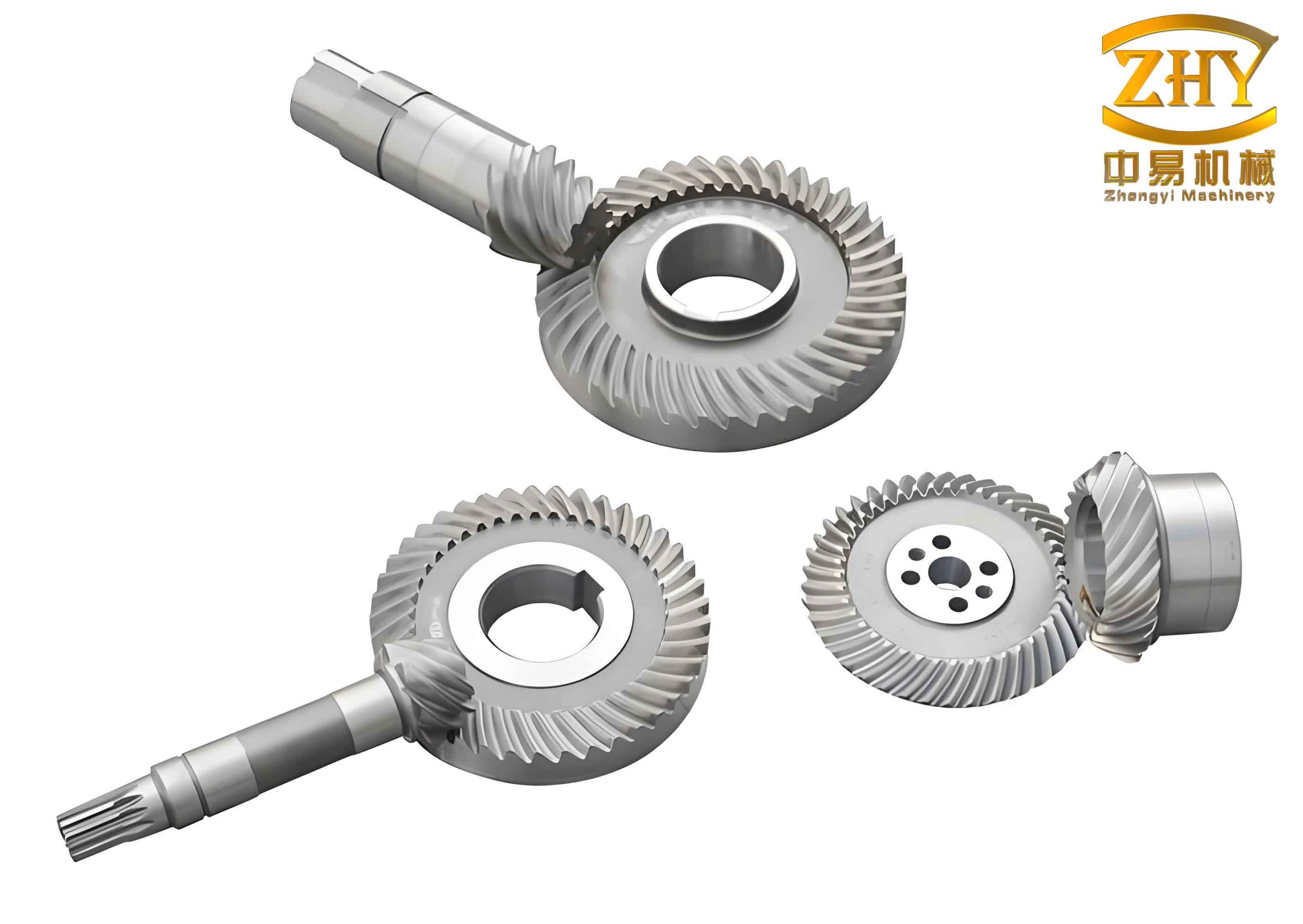
Mathematical Foundation for Hyperboloidal Gear Design
Geometric Relationships of the Pitch Cone
The fundamental task in designing a pair of hyperboloidal gears is to define their pitch cones. For gears with perpendicular yet offset axes, the relative motion is a screw motion. The theoretical pitch surfaces are hyperboloids of revolution. However, for practical design and manufacturing, these are approximated by two conjugate conical surfaces that are tangent at a specific point, known as the pitch point (P). The determination of this point and the associated cones is critical.
Let \( E \) be the offset distance (the shortest distance between the two axes). The geometry at the pitch point involves several key angles and distances, as derived from spatial relationships. The shaft angle is denoted by \( \Sigma \) (typically 90°). The offset angles in the axial planes of the gear and pinion are \( \epsilon \) and \( \eta \), respectively. The pitch cone angles are \( \delta_1 \) (pinion) and \( \delta_2 \) (gear). The pitch radii at the mean point are \( r_1 \) (pinion) and \( r_2 \) (gear), and the corresponding cone distances are \( R_1 \) and \( R_2 \).
The core geometric relationships governing the pitch cone setup are summarized by the following system of equations:
$$ E = r_2 \sin \epsilon + r_1 \sin \eta $$
$$ \tan \delta_2 = \frac{\sin \epsilon \tan \Sigma}{\sin \eta – \cos \epsilon \tan \Sigma \cot \eta} $$
$$ \tan \delta_1 = \frac{\sin \eta \tan \Sigma}{\sin \epsilon – \cos \eta \tan \Sigma \cot \epsilon} $$
$$ R_1 = \frac{r_1}{\sin \delta_1}, \quad R_2 = \frac{r_2}{\sin \delta_2} $$
The spiral angles \( \beta_1 \) and \( \beta_2 \) of the pinion and gear at the mean point, along with the offset angle in the pitch plane \( \epsilon’ \), are related by:
$$ \epsilon’ = \beta_1 – \beta_2 $$
$$ \sin \epsilon’ = \frac{\sin \Sigma \sin \epsilon}{\cos \delta_1} = \frac{\sin \Sigma \sin \eta}{\cos \delta_2} $$
A crucial parameter is the ratio-of-roll or velocity ratio factor \( k \), which relates the pitch radii and spiral angles:
$$ k = \frac{R_1 \cos \beta_1}{R_2 \cos \beta_2} = \frac{r_1 \cos \beta_1}{r_2 \cos \beta_2} = \cos \epsilon’ + \tan \beta_1 \sin \epsilon’ $$
Gleason Methodology for Geometric Parameter Calculation
The Gleason method provides a systematic, step-by-step procedure for calculating the geometric parameters of hyperboloidal gears. It starts with a set of initial conditions and performs iterative calculations to converge on a solution. The initial data typically includes:
- Number of pinion teeth \( z_1 \) and gear teeth \( z_2 \), or the gear ratio \( i = z_2/z_1 \).
- Shaft angle \( \Sigma \) (usually 90°).
- Offset distance \( E \).
- Face width of the gear \( b \).
- Mean spiral angle of the pinion \( \beta_{10} \).
- Cutter radius \( r_0 \).
The core of the Gleason calculation involves approximately 16 independent equations with roughly 20 unknown variables (like \( r_1, r_2, \delta_1, \delta_2, \beta_1, \beta_2, \epsilon, \eta \), etc.). To solve the system, four specific constraints or design decisions are implicitly or explicitly applied during the calculation sequence:
- Gear Pitch Diameter and Face Width: The outer pitch diameter of the gear \( D_2 \) is initially estimated. The mean pitch radius \( r_2 \) is linked to \( D_2 \), face width \( b \), and pitch cone angle \( \delta_2 \) by: $$ r_2 = 0.5D_2 – 0.5b \sin \delta_2 $$ The initial gear pitch cone angle is often estimated as: $$ \tan \delta_2′ = \frac{1.2 z_2 \sin \Sigma}{z_1 \cos \Sigma + z_2} $$
- Pinion Spiral Angle: An empirical formula gives the nominal pinion mean spiral angle: $$ \beta_{10} \approx 25 + \frac{5 z_2}{z_1} + \frac{90 E}{D_2} $$
- Cutter Radius: The calculated radius of curvature along the tooth length at the pitch point should match a standard cutter radius \( r_0 \).
- Iterative Refinement: The calculation proceeds through two main iterative loops. The first adjusts the ratio-of-roll \( k \) to make the calculated pinion spiral angle \( \beta_1 \) match the nominal value \( \beta_{10} \). The second iteration checks and adjusts parameters related to the cutter radius and the limiting curvature.
The Gleason method, while robust and widely used, has inherent limitations due to its sequential, formula-driven nature designed for manual calculation. These can lead to the pitch point not being precisely at the mid-face, discrepancies in the final spiral angle, and mismatches with standard cutter sizes.
A Novel Optimization-Based Design Approach
Building upon the Gleason foundation, a new design methodology is proposed that frames the problem as a unified system of equations solved via optimization techniques. Instead of a fixed sequence, all 20 key geometric parameters are treated as unknowns to be solved simultaneously from a system of 20 equations.
The system comprises the 16 fundamental geometric equations (like those for \( E, \delta_1, \delta_2, k \), etc.) plus four explicit constraint equations derived from the design requirements:
- The explicit pitch radius-face width relationship: \( r_2 = 0.5D_2 – 0.5b \sin \delta_2 \).
- The target pinion spiral angle: \( \beta_1 = \beta_{10} \).
- The standard cutter radius condition: \( r_0 = r_{0\_standard} \).
- The pitch cone angle consistency: \( \delta_2 = \delta_2′ \) (using a modified formula with a correction factor \( k_\delta \), e.g., initially 1.2).
This forms a nonlinear system. The problem is then recast as an optimization problem to minimize the deviations from the desired constraints. Defining a parameter vector \( \mathbf{X} = (k, \eta, k_\delta, …) \), an objective function \( F(\mathbf{X}) \) is constructed:
$$ F(\mathbf{X}) = (\beta_1 – \beta_{10})^2 + (\delta_2 – \delta_2′)^2 + (r_0 – r_{0\_standard})^2 $$
The goal is to find \( \mathbf{X} \) that minimizes \( F(\mathbf{X}) \), subject to the termination condition \( F(\mathbf{X}) \leq \epsilon_p \) (e.g., \( \epsilon_p = 10^{-4} \)). This is a nonlinear least-squares problem solvable by algorithms like the Gauss-Newton method. This approach ensures all constraints are met more precisely in a single, coordinated solution step.
Comparative Application Example
To validate the new method, its results are compared with the traditional Gleason method for two example gear sets from literature. The comparisons show that the optimization-based method achieves superior agreement with the initial design targets.
| Parameter | Gleason Result | New Method Result | Initial Target/Note |
|---|---|---|---|
| Pinion Spiral Angle \( \beta_1 \) | 50° 45′ | 50° 00′ | 50° 00′ |
| Gear Pitch Cone Angle \( \delta_2 \) | 73° 33′ | 74° 20′ | Initial Est.: 71° 42′ |
| Calculated Cutter Radius \( r_0 \) (mm) | 95.46 | 95.25 | Standard: 95.25 |
| Parameter | Gleason Result | New Method Result | Initial Target/Note |
|---|---|---|---|
| Pinion Spiral Angle \( \beta_1 \) | 49° 03′ | 49° 00′ | 49° 00′ |
| Gear Pitch Cone Angle \( \delta_2 \) | 75° 17′ | 75° 19′ | Initial Est.: 75° 29′ 34” |
| Calculated Cutter Radius \( r_0 \) (mm) | 203.00 | 203.20 | Standard: 203.20 |
The tables demonstrate that the new method effectively eliminates the error in the pinion spiral angle and matches the standard cutter radius exactly, while providing a more consistent solution for the pitch cone angle.
Implementation of a Parameterized Design System for Hyperboloidal Gears
Theoretical Tooth Profile: Spherical Involute
The true tooth profile of a hyperboloidal gear is a spherical involute, a complex space curve lying on the surface of a sphere centered at the cone apex. This arises because the mating motion of two cones is a spherical rotation. The spherical involute is generated by a great circle on a base cone rolling without slipping on the surface of a base sphere. The parametric equations for a spherical involute, derived through coordinate transformations from a rotating frame attached to the generating plane to a fixed frame, are as follows:
Let \( R_b \) be the cone distance (sphere radius), \( \theta \) be the base cone angle, \( \psi \) be the generating angle parameter, and \( \phi \) be the roll angle. The coordinates \((x, y, z)\) of a point on the spherical involute are:
$$ x = R_b (\sin \psi \cos \phi + \cos \theta \cos \psi \sin \phi) $$
$$ y = R_b (-\sin \psi \sin \phi + \cos \theta \cos \psi \cos \phi) $$
$$ z = R_b \cos \psi \sin \theta $$
where \( \phi = \psi / \sin \theta \). The base cone angle \( \theta \) is related to the pitch cone angle \( \delta \) and pressure angle \( \alpha \) by \( \sin \theta = \cos \alpha \sin \delta \).
Three-Dimensional Modeling in Pro/ENGINEER
Building an accurate 3D model of hyperboloidal gears is challenging due to the complex spatial tooth surfaces. The process within Pro/ENGINEER Wildfire 2.0 involves several key steps, leveraging its feature-based, parametric, and associative capabilities:
- Gear Blank Creation: The basic conical shape of the gear and pinion blanks are created via rotational protrusions. Critical parameters (e.g., pitch diameter, cone angle, face width) are defined as named parameters within Pro/E’s parameter table.
- Single Tooth Profile Generation: Using the “Curve from Equation” feature, the spherical involute equations are input to create the precise tooth flank curve on the outer (heel) and inner (toe) cone surfaces. The profile is completed by adding tip and root arcs and fillets to form a closed loop on each end.
- Single Tooth Creation: A variable-section sweep feature is used. The heel and toe profiles are designated as section trajectories, and a guide curve (representing the tooth length direction) directs the sweep, generating the solid, spatially curved tooth.
- Full Gear Model: The single tooth is patterned radially around the axis using the calculated number of teeth, completing the 3D model of the gear or pinion.
Throughout this process, all dimensions are driven by the previously defined parameters and their interrelationships (defined in Pro/E’s “Relations”), making the model fully parametric.
Secondary Development and Parameterization with Pro/TOOLKIT
To create an efficient and user-friendly design system, the generic Pro/E environment is customized via secondary development. Pro/TOOLKIT, the C-language based API from PTC, is used in conjunction with Microsoft Visual C++ 6.0. The chosen development mode is asynchronous, where the developed application runs as a separate executable that communicates with a running Pro/E session via remote procedure calls, allowing for more complex and independent application logic.
The parameterized system architecture follows this workflow:
- The VC++ application provides a graphical user interface (GUI) for inputting design requirements (power, speed, ratio, offset, etc.).
- The application runs the novel optimization-based geometric calculation algorithm to determine all gear parameters.
- Through Pro/TOOLKIT functions, the application connects to Pro/E, retrieves the pre-built template part models for the gear and pinion, and accesses their named parameters.
- The calculated new parameter values are written back to the Pro/E model parameters via Pro/TOOLKIT functions (e.g.,
ProParameterValueSet). - The application commands Pro/E to regenerate the model (
ProSolidRegenerate), instantly updating the 3D geometry according to the new parameters.
The system integrates several modules: a design input and calculation module, a database module (e.g., using Access) to store standard parameters and results, and the Pro/TOOLKIT interface module for model control. The main application interface guides the user through the entire process from initial data entry to the automatic generation of the 3D models for both the pinion and gear.
Kinematic Simulation and Analysis of the Hyperboloidal Gear Pair
Virtual Assembly
Before simulation, the individually modeled pinion and gear must be assembled virtually. Using Pro/E’s assembly mode with a bottom-up approach, the gear is placed first as a fixed component. The pinion is then assembled relative to it. The correct spatial relationship, defined by the offset distance \( E \) and the shaft angle \( \Sigma \), is established using assembly constraints such as “Mate” (for coaxiality of theoretical axes), “Offset” (to define \( E \)), and “Angle” (to set \( \Sigma \)). Proper assembly is critical to avoid interference and ensure correct meshing in the simulation.
Establishing the Motion Model in Pro/Mechanism
Pro/Mechanism is used to create a dynamic model of the assembled hyperboloidal gears. Key steps include:
- Defining Connections: The gear and pinion are connected to the ground (frame) using “Pin” joints, allowing only rotation about their respective axes.
- Defining the Gear Pair: A “Gear” connection is created between the two Pin joints. This connection defines the gear ratio based on the number of teeth (\( z_2 / z_1 \)) and ensures kinematic coupling.
- Applying Drivers: A servo motor is applied to the pinion’s Pin joint. The motor’s motion profile is defined (e.g., constant angular velocity).
- Setting up Loads and Gravity: To perform dynamic analysis, a resistive torque (load) can be applied to the gear’s axis, and gravity can be enabled to account for mass properties.
| Connection Type | Rotational DOF | Translational DOF | Description |
|---|---|---|---|
| Pin | 1 | 0 | Revolute joint, allows rotation about an axis. |
| Slider | 0 | 1 | Prismatic joint, allows translation along an axis. |
| Cylinder | 1 | 1 | Combines rotation and translation along an axis. |
| Gear | N/A | N/A | Kinematic constraint defining ratio between two pin joints. |
Simulation Execution and Results Analysis
With the motion model complete, kinematic and dynamic analyses are run. Two representative scenarios are examined: a low-speed, high-torque condition and a high-speed, lower-torque condition, typical of automotive final drive operation.
| Condition | Pinion Speed (rpm) | Gear Load Torque (Nm) | Simulation Time (s) |
|---|---|---|---|
| Low-Speed / High-Torque | 60 | 480 | 2 |
| High-Speed / Low-Torque | 2800 | 210 | 3 |
The simulation results produce graphs of angular velocity and torque over time. In both scenarios, the graphs show an initial transient period (approximately 0-1 second for the low-speed case and 0-2 seconds for the high-speed case) where the velocity and torque curves exhibit oscillations. This corresponds to the initial engagement and acceleration phase where inertia and meshing impacts cause dynamic fluctuations. After this transient period, the curves stabilize into steady, nearly constant lines, indicating smooth, steady-state operation of the hyperboloidal gear transmission.
These simulation results serve multiple purposes: they visually verify the correct meshing of the parameterized gear models without interference; they provide insight into the dynamic behavior during start-up; and they validate the overall design and assembly process. The consistency of the transient behavior patterns across different speed/load conditions reinforces the reliability of the models and the design methodology.
Conclusion
This work presents a comprehensive study on the design, modeling, and simulation of hyperboloidal gears. A new optimization-based geometric design method was proposed, addressing limitations of the traditional Gleason sequential approach by simultaneously solving for all parameters to meet multiple design constraints precisely. The mathematical foundation, including the derivation of the spherical involute, was established to support accurate modeling.
A fully parameterized CAD system was successfully implemented by performing secondary development on Pro/ENGINEER using Pro/TOOLKIT and Visual C++. This system integrates geometric calculation, automated 3D model generation, and design data management into a streamlined workflow. Finally, the virtual prototypes created by the system were assembled and subjected to kinematic and dynamic simulation in Pro/Mechanism, confirming their correct functional behavior and providing valuable dynamic performance data.
The integration of advanced geometric calculation, parametric CAD, and motion simulation forms a powerful framework for the efficient and reliable development of high-performance hyperboloidal gears, contributing to the ongoing advancement in the design and analysis of these critical mechanical components.