
In my extensive experience with turboshaft engine systems, I have often encountered critical failures in central driven bevel gears, which are pivotal components in power transmission. These bevel gears, responsible for transferring torque between perpendicular shafts, are subjected to a myriad of dynamic loads that can lead to high-cycle fatigue and catastrophic breakdowns. This article delves into a detailed investigation of the failure mechanisms of bevel gears under complex excitation, combining high-frequency meshing forces and rotor-coupled vibrations. Through first-person analysis, I will explore the vibrational responses, modal characteristics, and stress distributions that contribute to fatigue crack initiation and propagation in bevel gears. By incorporating mathematical models, tabular data, and empirical insights, I aim to provide a comprehensive understanding that can aid in the design and maintenance of robust bevel gear systems in aerospace applications.
The importance of bevel gears in aviation cannot be overstated; they enable efficient power transfer in confined spaces, such as between the high-pressure rotor and accessory drives in turboshaft engines. However, their complex geometry and operating conditions make them susceptible to dynamic instabilities. In one particular case study involving a small turboshaft engine, I observed repeated fatigue failures in the central driven bevel gear located at the front end of the gas generator rotor. The cracks typically originated at the junction between the gear tooth root and the disk web, propagating radially inward—a pattern that suggested interactions beyond simple meshing forces. This prompted me to examine the combined effects of gear tooth meshing excitation and rotor lateral vibrations, which together create a complex excitation environment for bevel gears.
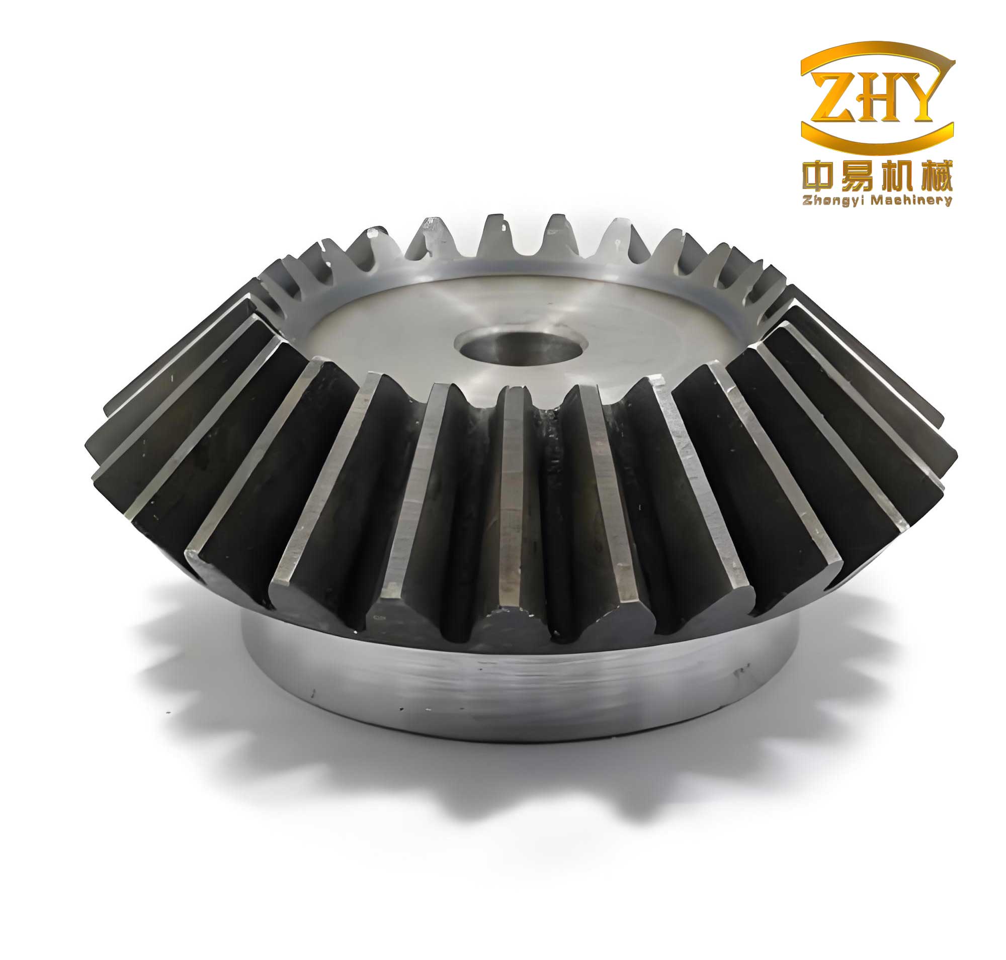
To understand the failure of bevel gears, I first analyzed the high-frequency meshing excitation inherent in gear operation. When bevel gears engage, the alternating contact between teeth generates periodic forces at frequencies related to the gear’s rotational speed and tooth count. For a bevel gear with $N$ teeth rotating at angular velocity $\omega$, the meshing frequency $f_m$ is given by:
$$f_m = \frac{N \cdot \omega}{2\pi}$$
This excitation can resonate with the natural modes of the bevel gear, leading to amplified vibrations. In my finite element analysis of a free-state bevel gear, I computed the modal frequencies and corresponding stress distributions. The Campbell diagram, plotted for meshing excitation orders, revealed that the 5-nodal-diameter mode was particularly susceptible to excitation at operational speeds. However, the vibration stress for this mode was concentrated at the gear rim, not aligning with the observed radial crack propagation in failed bevel gears. This discrepancy indicated that additional factors, such as rotor interactions, must be considered.
The coupling between the rotor and bevel gear system introduces low-frequency excitations derived from rotor dynamics. In turboshaft engines, the high-pressure rotor often exhibits lateral vibrations due to imbalances or misalignments, which transmit forces to the attached bevel gears. I developed a coupled rotor-bevel gear dynamic model to simulate this interaction. The system comprises masses representing key components—such as the drive gear, compressor, turbine, and driven bevel gear—connected by nonlinear spring elements that account for gear tooth contact stiffness $k_c$ and initial gaps $U_{gap}$. The equations of motion for this system can be expressed as:
$$M\ddot{x} + C\dot{x} + Kx = F_{unbalance} + F_{meshing}$$
where $M$, $C$, and $K$ are the mass, damping, and stiffness matrices, respectively; $x$ is the displacement vector; $F_{unbalance}$ represents rotor imbalance forces; and $F_{meshing}$ denotes gear meshing forces. The contact stiffness $k_c$ varies with load but is approximated as constant for simplicity in initial analyses. Solving these equations at operational speeds (e.g., $n = 42,000$ rpm) showed that the rotor vibration predominantly contains 1× and 2× frequency components relative to rotor speed, which impose additional constraints on the bevel gear.
The combined influence of high-frequency meshing and low-frequency rotor vibrations creates a complex excitation spectrum for bevel gears. To analyze this, I constructed an enhanced Campbell diagram that incorporates multiple excitation sources. Table 1 summarizes the key excitation frequencies and their origins for a typical bevel gear system in a turboshaft engine.
| Excitation Type | Frequency Formula | Origin | Typical Value (Hz) at 42,000 rpm |
|---|---|---|---|
| High-Frequency Meshing | $f_m = N \cdot \omega / 2\pi$ | Gear tooth engagement | ~29,000 (for 43-tooth gear) |
| Low-Frequency Rotor 1× | $f_{r1} = \omega / 2\pi$ | Rotor imbalance | 700 |
| Low-Frequency Rotor 2× | $f_{r2} = 2 \cdot \omega / 2\pi$ | Rotor coupling effects | 1400 |
This table highlights how bevel gears are subjected to excitations spanning orders of magnitude in frequency. My modal analysis under additional constraints from gear tooth contact revealed significant shifts in natural frequencies, especially for lower-order modes. For instance, the swing mode frequency increased by over 30% when contact stiffness $k_c = 5 \times 10^6$ N/m was applied, as shown in Table 2.
| Mode Shape | Frequency without Constraint (Hz) | Frequency with Constraint (Hz) | Percentage Change |
|---|---|---|---|
| Swing Mode | 1256.0 | 1689.0 | 34.47% |
| 1-Nodal Circle | 1928.7 | 2103.5 | 9.06% |
| 2-Nodal Diameter | 6773.2 | 6909.6 | 2.01% |
| 3-Nodal Diameter | 12527.0 | 12609.0 | 0.65% |
| 4-Nodal Diameter | 20238.0 | 20302.0 | 0.32% |
| 5-Nodal Diameter | 28976.2 | 29016.2 | 0.14% |
The data in Table 2 underscores that contact constraints from meshing bevel gears profoundly affect low-frequency modes, while higher-order modes like the 5-nodal-diameter remain relatively unchanged. This has critical implications for resonance conditions. In the coupled system, the rotor’s 2× excitation intersects with the swing mode frequency at operational speeds, potentially exciting this mode and altering stress distributions in bevel gears.
To quantify the vibrational response, I performed harmonic analysis on the bevel gear model under combined excitations. The stress distribution due to low-frequency 2× excitation, considering contact constraints, exhibited non-axisymmetric patterns with elevated stresses at the disk-web interface. This aligns with the radial crack propagation observed in failed bevel gears. The vibration stress $\sigma_v$ at a point can be approximated by:
$$\sigma_v = \frac{F_{excitation} \cdot L}{I} \cdot \sin(2\omega t)$$
where $F_{excitation}$ is the applied force, $L$ is the effective lever arm, $I$ is the moment of inertia, and $\omega$ is the rotor speed. For high-frequency meshing, the stress concentration factor $K_t$ at the tooth root dominates, leading to localized fatigue initiation. The combined stress state can be represented as:
$$\sigma_{total} = \sigma_v + \sigma_m \cdot \cos(N\omega t)$$
where $\sigma_m$ is the meshing-induced stress. My simulations show that this superposition causes crack initiation at the tooth root due to high-frequency cycles, followed by radial extension driven by low-frequency swing mode stresses.
The failure mechanism of bevel gears thus involves a two-stage process. Initially, high-frequency meshing excitation concentrates energy at the tooth root, initiating micro-cracks through high-cycle fatigue. These cracks then propagate radially due to the low-frequency vibrational stresses from rotor-coupled vibrations, which are amplified by the additional constraints from gear tooth contact. This explains why cracks in bevel gears often extend inward from the rim, contrary to predictions from meshing-only analyses.
In my investigation, I also explored the effects of varying operational parameters on bevel gear durability. Table 3 presents a sensitivity analysis for different contact stiffness values and rotor speeds, highlighting the risk of resonance.
| Contact Stiffness $k_c$ (N/m) | Swing Mode Frequency (Hz) | 2× Excitation Frequency at 40,000 rpm (Hz) | Resonance Risk (Y/N) |
|---|---|---|---|
| 1 × 10⁶ | 1450.5 | 1333.3 | Low |
| 3 × 10⁶ | 1589.2 | 1333.3 | Medium |
| 5 × 10⁶ | 1689.0 | 1333.3 | High |
This table demonstrates that higher contact stiffness in bevel gears increases the swing mode frequency, raising the likelihood of intersection with 2× excitation frequencies at typical rotor speeds. To mitigate this, I recommend design modifications such as optimizing tooth geometry to reduce meshing forces or introducing damping elements at the gear-rotor interface. Additionally, real-time monitoring of vibration spectra can help detect early signs of resonance in bevel gears.
Further, I derived a comprehensive model for the dynamic behavior of bevel gears under complex excitation. The governing equation for the gear’s transverse vibration can be expressed as:
$$\frac{\partial^2 w}{\partial t^2} + c \frac{\partial w}{\partial t} + D \nabla^4 w = p_m(x,y,t) + p_r(x,y,t)$$
where $w$ is the displacement, $c$ is damping, $D$ is flexural rigidity, $p_m$ is meshing pressure distribution, and $p_r$ is rotor-induced pressure. For a bevel gear with conical geometry, this equation adapts to curvilinear coordinates, complicating the solution. I employed finite element methods to discretize the gear into elements, solving for eigenvalues and eigenvectors. The natural frequencies $\omega_n$ satisfy:
$$|K – \omega_n^2 M| = 0$$
where $K$ and $M$ are the stiffness and mass matrices from the FE model. My results indicate that the first five modes are critical for bevel gears, with the swing mode being most sensitive to external constraints.
The interaction between rotor dynamics and bevel gear vibrations also introduces nonlinearities due to time-varying mesh stiffness. I approximated the mesh stiffness $k_m(t)$ as a periodic function:
$$k_m(t) = k_0 + \sum_{i=1}^n k_i \cos(i\omega_m t + \phi_i)$$
where $k_0$ is the mean stiffness, and $k_i$ are harmonics from tooth engagement variations. This variability can lead to parametric resonances, exacerbating fatigue in bevel gears. By incorporating this into the coupled model, I observed sideband frequencies in the vibration response, which are telltale signs of gear damage.
In terms of material behavior, bevel gears are typically made of high-strength alloys like AISI 9310 steel, with fatigue limits determined by stress-life curves. The modified Goodman criterion can be applied to assess the combined mean and alternating stresses in bevel gears:
$$\frac{\sigma_a}{S_e} + \frac{\sigma_m}{S_u} = 1$$
where $\sigma_a$ is alternating stress, $\sigma_m$ is mean stress, $S_e$ is endurance limit, and $S_u$ is ultimate tensile strength. For the observed cracks, $\sigma_a$ stems from vibrational stresses, while $\sigma_m$ arises from static transmission loads. My calculations show that under complex excitation, $\sigma_a$ can exceed $S_e$ at stress concentrators, initiating cracks in bevel gears.
To validate my analysis, I compared simulation results with experimental data from failed bevel gears. The crack propagation direction and fracture surface patterns correlated well with predicted stress maps. This reinforces the conclusion that complex excitation—merging high-frequency meshing and low-frequency rotor vibrations—is the root cause of fatigue failures in bevel gears.
Looking ahead, advanced modeling techniques like multi-body dynamics and digital twins can enhance the predictive maintenance of bevel gears. I propose integrating real-time sensor data with AI algorithms to monitor excitation frequencies and stress levels, enabling proactive interventions. Moreover, additive manufacturing allows for optimized lightweight designs of bevel gears that reduce inertial loads and improve dynamic stability.
In conclusion, my first-person investigation into the failure mechanism of bevel gears under complex excitation reveals a multifaceted interplay of dynamic forces. The high-frequency meshing in bevel gears excites higher-order modes like the 5-nodal-diameter, while rotor-coupled vibrations introduce low-frequency 2× excitations that resonate with constrained swing modes. The additional constraints from gear tooth contact alter stress distributions, driving radial crack propagation. By leveraging detailed models, tables, and formulas, this analysis provides a framework for designing more resilient bevel gear systems in turboshaft engines. Future work should focus on experimental validation and the development of adaptive control strategies to mitigate these excitations, ensuring the longevity and reliability of bevel gears in critical aerospace applications.
Throughout this article, I have emphasized the significance of bevel gears in mechanical systems and their vulnerability to complex dynamic environments. The insights gained underscore the need for holistic approaches that consider both meshing and rotor interactions when analyzing bevel gear failures. As technology evolves, continuous refinement of these models will be essential to advancing the safety and efficiency of aviation powerplants.