
In this study, I focus on the roll forming of small module helical gears with a module below 1 mm, which are widely used in precision instruments, automotive components, aerospace systems, and electromechanical devices. Conventional manufacturing routes such as gear shaping, hobbing, and multi-axis cutting remove material from the blank, which wastes raw material and interrupts the metal fiber flow line. Powder metallurgy suffers from poor powder flowability, while forging demands excessive loads and suffers from demolding difficulties. To address these limitations, I investigate an axial rolling process that uses external meshing double rolling wheels and a free indexing strategy. My objective is to establish a reliable bite-in model, design suitable rolling wheels, and determine process parameters that guarantee both forming accuracy and production efficiency for helical gears.
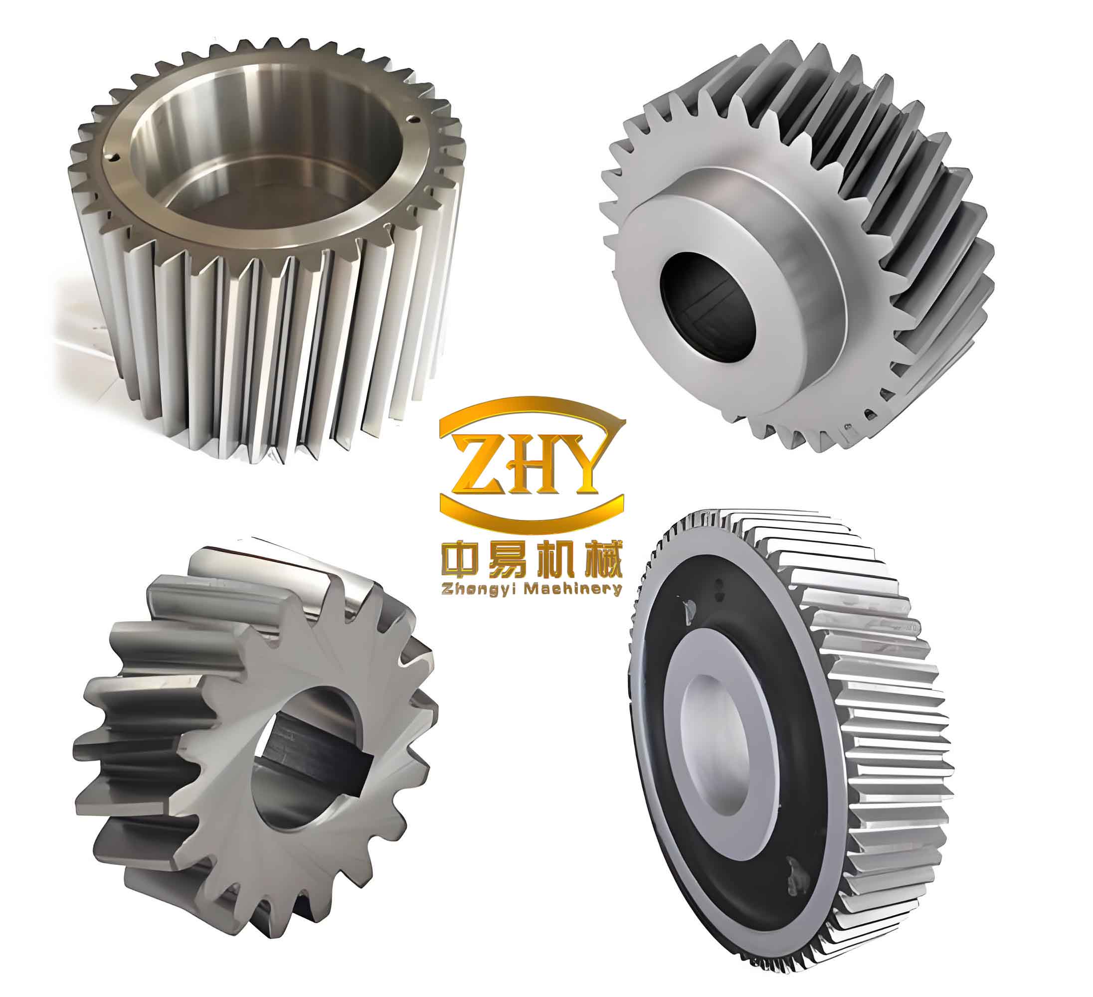
The axial rolling of helical gears is based on the principle of gear meshing, similar to a knurling process. The rolling wheels press against the workpiece, causing plastic deformation. As the workpiece is bitten into by the rolling wheels, the surface is uniformly divided into the target number of teeth. The rolling wheels and workpiece perform a generating motion, and the rolling depth increases continuously. Under the extrusion of the rolling wheel teeth, the workpiece material flows along the tooth surfaces, and the tooth height gradually increases until the full tooth profile of the helical gears is formed. The helical gears produced by this method retain a continuous metal fiber flow line, which enhances tooth strength compared with cut gears.
1. Forming Scheme and Indexing Strategy
I selected an external meshing configuration with double rolling wheels and axial feed, combined with free indexing. Internal meshing rolling offers a larger contact area and higher contact ratio, but internal gear dies are difficult to manufacture and complicate machine tool design. The rack rolling method requires the die to travel a distance greater than the pitch circle circumference of the workpiece, and the forming force it provides is relatively small. Single rolling wheel rolling tends to cause radial deformation of the workpiece due to unbalanced loading. Three rolling wheel rolling imposes a minimum outer diameter requirement that small module helical gears cannot satisfy. Therefore, the double rolling wheel external meshing scheme is the most suitable for helical gears with small modules.
Regarding the feed mode, I adopted axial feed rather than radial feed. Radial feed requires the rolling wheel tooth width to exceed the workpiece tooth width, resulting in a large contact area and high forming force. Moreover, the center distance changes during radial feed, which alters the transmission ratio and degrades the generating motion, thereby reducing forming accuracy. Axial feed avoids these problems. The rolling wheel is designed with an axial increment structure, in which part of the tooth tip surface forms a taper angle with the roller axis. The tooth height increases gradually along the axial direction until the normal tooth profile is reached. This taper design enables the workpiece to be bitten in smoothly and the material to flow into the tooth tip rather than toward the end faces.
The rolling wheel can be divided into a biting-in section, a finishing section, and an exit section along the axial direction. In the biting-in section, the blank is bitten in and correctly indexed. In the finishing section, the rolling wheel maintains a generating motion with the workpiece at full tooth height, improving the tooth profile and closing any rabbit-ear defect at the tooth tip. The exit section resembles a chamfer and prevents scratches on the workpiece surface when the rolling wheel disengages. Because helical gears generate a significant axial force during meshing, the bite-in condition is more demanding than for spur gears. Correct indexing in the biting-in section is the foundation for producing helical gears with sufficient accuracy.
2. Workpiece Blank Size Determination
The material selected for the workpiece is a copper-zinc alloy designated C27000, equivalent to H65. Its mechanical properties are summarized in the following table.
| Standard | Type | Relative Elongation (%) | Hardness |
|---|---|---|---|
| GB/T 2059-2000 | Copper-zinc alloy | ≥25 | 85–145 HV |
I determined the initial diameter of the workpiece blank using the principle of constant plastic volume, assuming that the material undergoes only plastic deformation and no axial displacement. The initial radius can be expressed as:
$$r_1 = \sqrt{\frac{V}{\pi W}}$$
where \(V\) is the volume of the formed helical gears and \(W\) is the thickness. Based on the required dimensions, the end face area of the workpiece is 26.1 mm², and the calculated initial diameter of the blank is 5.7636 mm. The target helical gears have the following parameters.
| Parameter | Specification |
|---|---|
| Normal module | 0.5 mm |
| Normal pressure angle | 20° |
| Number of teeth | 11 |
| Helix direction | Right-hand |
| Helix angle | 20° |
| Profile shift coefficient | 0 |
| Reference diameter | 5.853 mm |
| Root diameter | 4.603 mm |
| Tip radius | R0.15 (0, −0.08) |
| Root radius | R0.15 (0.05, −0.05) |
3. Force Analysis During the Biting-In Process
Before the rolling wheel bites into the workpiece, the blank is a smooth cylinder and cannot mesh with the rolling wheel. During the biting-in stage, the rolling wheel must press uniform indentations on the workpiece surface to divide the teeth. Because I adopted free indexing, the workpiece is driven by the pressure and friction from the rolling wheel. To avoid slipping and incorrect indexing, the resultant torque acting on the workpiece must be greater than zero, and the resultant force in the feed direction must also be greater than zero. These two conditions define the bite-in criteria for the rolling wheels.
I established a coordinate system with the workpiece axis as the \(Z\)-axis. The forces acting on the workpiece in the normal plane of the helix can be decomposed into axial and tangential components. The axial components of the tooth flank pressure \(F_1\) and tooth tip pressure \(F_2\) are:
$$F_{1z} = F_1 \sin\alpha,\quad F_{2z} = F_2 \sin\alpha$$
The corresponding frictional forces are \(F_{1f}\) and \(F_{2f}\), and their axial components are:
$$F_{1fz} = F_{1f} \sin\alpha,\quad F_{2fz} = F_{2f} \sin\alpha$$
Denoting the torques generated by these forces about the workpiece axis as \(M_1\), \(M_2\), \(M_{1f}\), and \(M_{2f}\), the bite-in conditions can be written as:
$$M_1 + M_2 + M_{1f} + M_{2f} > 0$$
$$F_{1z} + F_{2z} + F_{1fz} + F_{2fz} > 0$$
Based on the geometric relationship between the rolling wheel and the workpiece in the normal plane, the torques and axial forces can be expressed as integrals over the contact width. The tooth flank pressure is:
$$F_1 = \int_{0}^{x_1} f(x)\,dx$$
and the tooth tip pressure is:
$$F_2 = \int_{0}^{x_1} g(x)\,dx$$
where \(x_1\) is the maximum contact width along the helix normal plane. These expressions provide the basis for constructing the bite-in condition model for helical gears.
4. Stress and Strain Analysis Using the Slip-Line Field Method
To solve for the average stresses on the contact surfaces, I used the slip-line field method, which is rigorous for plane strain problems. I assumed that the deformation on the helix normal plane satisfies the plane strain condition, meaning that material flow occurs only within parallel planes and is identical in each plane. The \(z\)-direction strain is zero, so the \(z\)-direction is a principal direction.
For the plane strain condition, the normal stress in the \(z\)-direction is equal to the mean stress:
$$\sigma_z = \sigma_m = \frac{\sigma_1 + \sigma_3}{2}$$
The yield condition gives:
$$K = \frac{\sigma_1 – \sigma_3}{2}$$
where \(K\) is the maximum shear stress, equal to the yield stress of the material. For C27000, the tensile strength ranges from 340 to 460 MPa, and I used the maximum value of 460 MPa to ensure reliability.
The slip-line field in the contact region was constructed by approximating the involute curvature as a straight line. The contact region was divided into uniform stress fields and centered fan fields. Using the Hencky stress equations, the mean stress along the slip lines can be related to the angular change. The average normal stress on the tooth tip contact surface is:
$$p_1 = 2K\left(1 – \frac{1}{2}\left(\frac{\pi}{2} – \phi_c\right) + \frac{1}{2}\sqrt{1 – m^2} – \frac{m}{2}\right)$$
and the average normal stress on the tooth flank contact surface is:
$$p_2 = 2K\left(1 – \frac{1}{2}\left(\frac{\pi}{2} – \phi_a\right) + \frac{1}{2}\sqrt{1 – m^2} – \frac{m}{2}\right)$$
where \(\phi_c\) and \(\phi_a\) are geometric angles depending on the rolling wheel and workpiece dimensions, and \(m\) is the shear friction coefficient, taken as 0.2. These stresses are used to compute the contact forces and the resulting torques and axial forces for the bite-in condition model.
5. Bite-In Condition Model and Influencing Factors
The contact forces are obtained by multiplying the average stresses by the contact areas:
$$F_1 = S_1 p_1,\quad F_2 = S_2 p_2$$
The frictional forces follow the Coulomb friction law:
$$F_{1f} = \mu_1 F_1,\quad F_{2f} = \mu_2 F_2$$
where \(\mu_1 = \mu_2 = 0.23\). Substituting these into the bite-in inequalities gives the torque condition:
$$F_1 (d_1 – \mu_1 d_{f1}) + F_2 (d_2 – \mu_2 d_{f2}) > 0$$
and the axial force condition:
$$F_1 (1 – \mu_1) \sin\alpha + F_2 (1 – \mu_2) \sin\alpha > 0$$
I solved this model using MATLAB and analyzed the influence of the rolling wheel tooth number \(z_1\) and taper angle \(\eta\). The results show that the torque and axial force are negatively correlated with both the tooth number and the taper angle. The torque condition is satisfied when the tooth number is below 122, while the axial force condition is satisfied when the tooth number is below 119 for the selected taper angle range. These findings directly inform the design of the rolling wheel for helical gears.
6. Simulation Verification
I built a finite element model using Deform-3D to simulate the rolling of small module helical gears. The workpiece was set as a plastic body with material C26000, which has properties similar to C27000. The rolling wheels were treated as rigid bodies. The friction between the workpiece and rolling wheels was modeled as shear friction with a coefficient of 0.2. The mesh was generated with 157,353 elements.
The motion settings were determined based on the transmission ratio and the axial feed speed. For a rolling wheel rotation speed of 0.5 rad/s, the workpiece rotation speed is 5.045 rad/s, and the axial feed speed is 1.61 mm/s. The simulation results show that the material flow occurs primarily along the normal direction of the contact surface, confirming the plane strain assumption. The stress distribution and torque evolution during the process verify the accuracy of the bite-in condition model.
I also performed simulations with different rolling wheel tooth numbers and taper angles. The results confirm that the torque and axial force decrease with increasing tooth number, and the axial force decreases with increasing taper angle, consistent with the theoretical model. The following table summarizes the rolling wheel tooth numbers and the corresponding simulation parameters.
| Tooth number | Transmission ratio | Rolling wheel speed | Workpiece speed | Feed speed |
|---|---|---|---|---|
| 79 | 11/79 | 0.5 | 3.5909 | 1.2832 |
| 87 | 11/87 | 0.5 | 3.9545 | 1.4132 |
| 111 | 11/111 | 0.5 | 5.0454 | 1.8030 |
The simulation results for torque and axial force under different tooth numbers and taper angles are summarized below.
| Tooth number | Bite-in torque (N·mm) | Maximum axial force (N) |
|---|---|---|
| 79 | 90.9 | 705.2 |
| 87 | 75.4 | 686.7 |
| 99 | 61.9 | 678.6 |
| 111 | 54.8 | 654.3 |
| Taper angle | Bite-in torque (N·mm) | Maximum axial force (N) |
|---|---|---|
| 3.5° | 62.7 | 663.2 |
| 4.5° | 61.4 | 678.6 |
| 5.5° | 58.8 | 689.9 |
I also studied the effect of rolling wheel rotation speed. The results show that as the rotation speed increases, the axial force and forming force also increase, which is beneficial for ensuring the workpiece feed but may reduce forming accuracy. Therefore, an optimal rotation speed must balance efficiency and precision.
7. Rolling Wheel Design for Helical Gears
I derived the tooth profile equations for the rolling wheel based on the meshing principle. The right-side tooth surface of the helical gears in the workpiece coordinate system is given by:
$$x_1 = r_b \left[\sin(\theta_K + \varphi) – \theta_K \cos(\theta_K + \varphi)\right]$$
$$y_1 = r_b \left[\cos(\theta_K + \varphi) + \theta_K \sin(\theta_K + \varphi)\right]$$
$$z_1 = \sqrt{x_1^2 + y_1^2} \tan\beta$$
where \(r_b\) is the base circle radius, \(\theta_K\) is the involute parameter, \(\varphi\) is the angular position, and \(\beta\) is the helix angle. The left-side tooth surface is obtained similarly with appropriate sign changes. The rolling wheel tooth profile is obtained by coordinate transformation and application of the meshing equation:
$$v_0 \cdot n_{14} = 0$$
where \(v_0\) is the relative velocity between the rolling wheel and workpiece, and \(n_{14}\) is the normal vector of the tooth surface.
For the rolling wheel material, I selected DC53, a cold work die steel with high strength, excellent toughness, and hardness of 62–63 HRC after heat treatment. Its properties are listed below.
| Parameter | Value |
|---|---|
| Elastic modulus | 212.64 GPa |
| Yield strength | 1442 MPa |
Based on the bite-in condition model and simulation results, I designed the rolling wheel with 113 teeth, a taper angle of 3.5°, and a tooth thickness of 20 mm. The tooth number was selected to be a prime number relative to the workpiece tooth number to avoid periodic errors and ensure uniform wear. The taper angle was chosen to satisfy the bite-in condition while maintaining sufficient finishing section length.
I checked the bending fatigue strength of the rolling wheel tooth root using the following formula for helical gears:
$$\sigma_F = \frac{2K_F T_1 Y_{Fa} Y_{Sa} Y_\varepsilon Y_\beta}{\phi_D m_n^3 z_1^2} \leq [\sigma_F]$$
The parameters used in the calculation are listed below.
| Parameter | Value |
|---|---|
| Load coefficient \(K_F\) | 2.400 |
| Tooth form factor \(Y_{Fa}\) | 2.28 |
| Stress correction factor \(Y_{Sa}\) | 1.73 |
| Contact ratio factor \(Y_\varepsilon\) | 0.68 |
| Helix angle factor \(Y_\beta\) | 0.90 |
| Face width factor \(\phi_D\) | 0.72 |
| Normal module \(m_n\) | 0.5 mm |
| Tooth number \(z_1\) | 99 |
| Allowable stress \([\sigma_F]\) | 350 MPa |
The calculated bending stress is 92.799 MPa, which is well below the allowable stress of 350 MPa, confirming that the designed rolling wheel meets the strength requirements for helical gears rolling.
8. Experimental Study on Forming Accuracy
I conducted rolling experiments on a CNC thread rolling machine with a maximum rolling force of 235 kN and a spindle speed range of 0–150 rpm. The rolling wheel phase was adjusted before each experiment to ensure that the indentations from both wheels coincided, which is essential for correct indexing of the helical gears. The workpiece blank length was increased to 12 mm to reduce the material loss at the ends and improve the effective tooth length.
I tested four rolling wheel rotation speeds: 20, 25, 30, and 35 rpm. The tooth profile and tooth direction errors were measured for each group. The results are summarized in the following tables.
| Measurement | Profile deviation (µm) | DIN grade |
|---|---|---|
| Left flank maximum | 5.3 | 6 |
| Left flank average | 3.5 | 5 |
| Right flank maximum | 5.7 | 8 |
| Right flank average | 4.5 | 7 |
| Measurement | Profile deviation (µm) | DIN grade |
|---|---|---|
| Left flank maximum | 10.2 | 8 |
| Left flank average | 5.4 | 6 |
| Right flank maximum | 10.5 | 8 |
| Right flank average | 6.5 | 7 |
| Measurement | Profile deviation (µm) | DIN grade |
|---|---|---|
| Left flank maximum | 14.5 | 10 |
| Left flank average | 11.0 | 9 |
| Right flank maximum | 11.5 | 8 |
| Right flank average | 9.0 | 8 |
| Measurement | Profile deviation (µm) | DIN grade |
|---|---|---|
| Left flank maximum | 23.0 | 11 |
| Left flank average | 15.3 | 10 |
| Right flank maximum | 17.9 | 9 |
| Right flank average | 11.1 | 8 |
The tooth direction errors were also measured, and the results are summarized below.
| Rotation speed (rpm) | Left flank average (µm) | Right flank average (µm) | Overall DIN grade |
|---|---|---|---|
| 20 | 5.8 | 5.3 | 5–8 |
| 25 | 10.0 | 6.2 | 5–8 |
| 30 | 12.8 | 10.3 | 7–9 |
| 35 | 12.2 | 11.9 | 8–10 |
The experimental results show that when the rotation speed is 20 and 25 rpm, the forming accuracy meets the requirement of grade 8 or better. When the rotation speed exceeds 25 rpm, the tooth profile and tooth direction errors increase significantly. At 30 and 35 rpm, the accuracy deteriorates noticeably, and the rolling wheel exhibits visible wear after processing 59 workpieces. The excessive rotation speed leads to a larger rolling depth per unit time, causing severe material flow and excessive forming force, which in turn affects the forming accuracy of the helical gears and accelerates tool wear.
Considering both production efficiency and tool life, I selected a rolling wheel rotation speed of 20 rpm for the axial rolling of small module helical gears. This speed ensures that the forming accuracy meets the grade 8 requirement, with the possibility of achieving grade 7 after subsequent finishing operations.
9. Conclusions
In this study, I investigated the axial rolling process for small module helical gears using external meshing double rolling wheels and free indexing. The main conclusions are as follows.
First, I established the bite-in condition model for helical gears rolling based on the force analysis in the helix normal plane and the slip-line field method. The model reveals that the workpiece must experience a positive resultant torque and a positive resultant axial force to be successfully bitten in. The torque and axial force are negatively correlated with the rolling wheel tooth number and taper angle.
Second, I determined the design parameters of the rolling wheel through theoretical analysis and finite element simulation. The rolling wheel was designed with 113 teeth, a taper angle of 3.5°, and a tooth thickness of 20 mm. The material DC53 was selected for its high strength and wear resistance. The bending fatigue strength of the tooth root was verified to be within the safe range.
Third, I conducted rolling experiments on small module helical gears with different rotation speeds. The results show that the forming accuracy meets grade 8 requirements when the rotation speed is 20–25 rpm. Higher speeds lead to increased forming forces, greater material flow instability, and accelerated tool wear. The optimal rotation speed of 20 rpm was selected to balance accuracy, efficiency, and tool life.
The research methods and findings of this study provide a theoretical basis and practical guidance for the industrial production of small module helical gears. The axial rolling process with double rolling wheels and free indexing offers a promising alternative to conventional cutting and powder metallurgy methods, enabling efficient and high-quality manufacturing of helical gears for precision instruments and other applications.