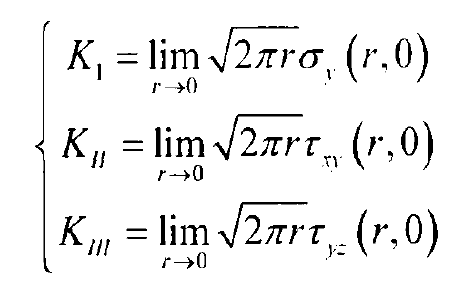
According to the formula, the stress intensity factors Ki, Kii and kiII are mainly used to characterize the stress field intensity at the crack tip, which is independent of the coordinates (x, y). The stress state near the crack tip is determined by the loading mode, load, crack length and crack geometry. In 1957, Irwin proposed the stress intensity factor Fracture Criterion for ideal linear elastic materials:
For mode I crack, when K1 reaches the critical value KC, the crack initiation and propagation occurs, where KC is called the material fracture toughness. Under plane strain, the material in front of the open crack tip is in triaxial tension: σ y= σ x, σ z=v( σ y+ σ x)。 In the case of plane stress, the material in front of the crack tip is in a biaxial stress state: σ y= σ x, σ z=0。 Therefore, in the case of plane strain, the crack is easier to expand.
For most engineering materials, there is a plastic zone at the crack tip. As shown in the figure, in the plastic zone, the stress-strain state is completely different from the linear elastic solution. If the size of the plastic zone is sufficiently small and completely surrounded by the dominant zone controlled by the stress intensity factor K field, the stress-strain field in the plastic zone will be controlled by the K field. Even if the geometry, loading mode and crack size of the two samples are different, if the stress intensity factors of the two samples are equal, the stress-strain field near the crack tip is the same. KC is mainly determined by the plastic work at the crack tip, and generally speaking, KC increases with the subcritical propagation of the crack Δα This produces a crack propagation resistance curve.
In fracture mechanics, solving crack stress intensity factor is a very important content. There are many methods to solve the stress intensity factor, which can be divided into two categories: the first is the theoretical calculation method, including analytical method and numerical method; The second is the test method, including standard test and actual measurement method. There are several methods in each category: the analytical methods include Westergaard stress function method, kolosov Muskhelishvili complex variable function method, integral transformation method, Green function method, etc; Numerical methods include finite difference method (FDM), boundary collocation method (bgnp), finite element method (FEM), boundary element method (BEM), etc; Standard Test refers to the basic test with mechanical specifications; The measurement methods include flexibility method, grid method, photoelastic method, laser holography, laser speckle method and moire method. The analytical method can only calculate simple problems, and the measured method is often subject to many restrictions. The numerical method has good application prospects. The finite element method is not limited by the geometry and load form of cracked body, and is widely used in fracture mechanics. The finite element method can be divided into direct method and indirect method. The direct method is to solve the approximate value of the stress intensity factor according to the relationship between the stress, displacement and the stress intensity factor scale at the crack tip. In the indirect method, some intermediate quantities, such as strain energy release rate G or J integral, are obtained by the finite element method, and then the ruler is derived according to the relationship between the stress intensity factor and these parameters.


