
In the field of mechanical transmission, worm gear pairs are among the most commonly used components. The manufacturing process of worm gears is complex, and the quality of the finished product is highly dependent on the rationality of the process planning. To overcome the tediousness of manual process planning and to ensure consistent quality, I developed a Computer-Aided Process Planning (CAPP) system for worm and gear parts. The core challenge lies in how to effectively represent and input part information into the computer. Based on my analysis of existing CAPP systems, I proposed a feature-based information description method for worm gears. The part information is first captured through a scanner, then processed by pattern recognition to extract feature vectors, and finally fed into a neural network for learning and training. This approach provides a practical solution suitable for the current industrial environment in many manufacturing facilities.
Part Information Description and Feature-Based Representation
For a typical part, a feature is a collection of information describing a specific geometric shape and its associated attributes such as material, precision, and surface finish. Features like holes, slots, bosses, chamfers, etc., can conveniently describe the geometry and provide necessary and sufficient information for machining, analysis, and other engineering applications. However, low-level geometric definitions (e.g., points, lines, surfaces) cannot capture non-geometric information (e.g., process data, assembly relationships, tolerances, material properties, functional requirements). This gap is bridged by the concept of a feature unit, which encapsulates a set of features. A feature unit can include several primary features, auxiliary features, datum features, and transition features. Depending on the actual manufacturing resources and the needs of part fabrication, inspection, and scheduling, a feature unit may consist of a single basic shape feature or all the features of the entire part. Generally, a part is decomposed into multiple feature units, represented as:
$$ \text{Part Features} = FU_1 + FU_2 + \dots + FU_n = \sum_{i=1}^{n} FU_i $$
Each feature unit can be further described by a feature matrix that captures both geometric and technological attributes. This hierarchical representation allows the CAPP system to efficiently reason about machining processes, cutting tool selection, and sequencing. In my system, the information input relies on scanning technology followed by pattern recognition, which extracts feature vectors from the scanned image. These vectors then drive the neural network to classify the part into a predefined family. The feature-based model thus serves as the bridge between raw geometric data and the high-level process knowledge required for automatic planning.
Shape Features of Worm and Gear Parts
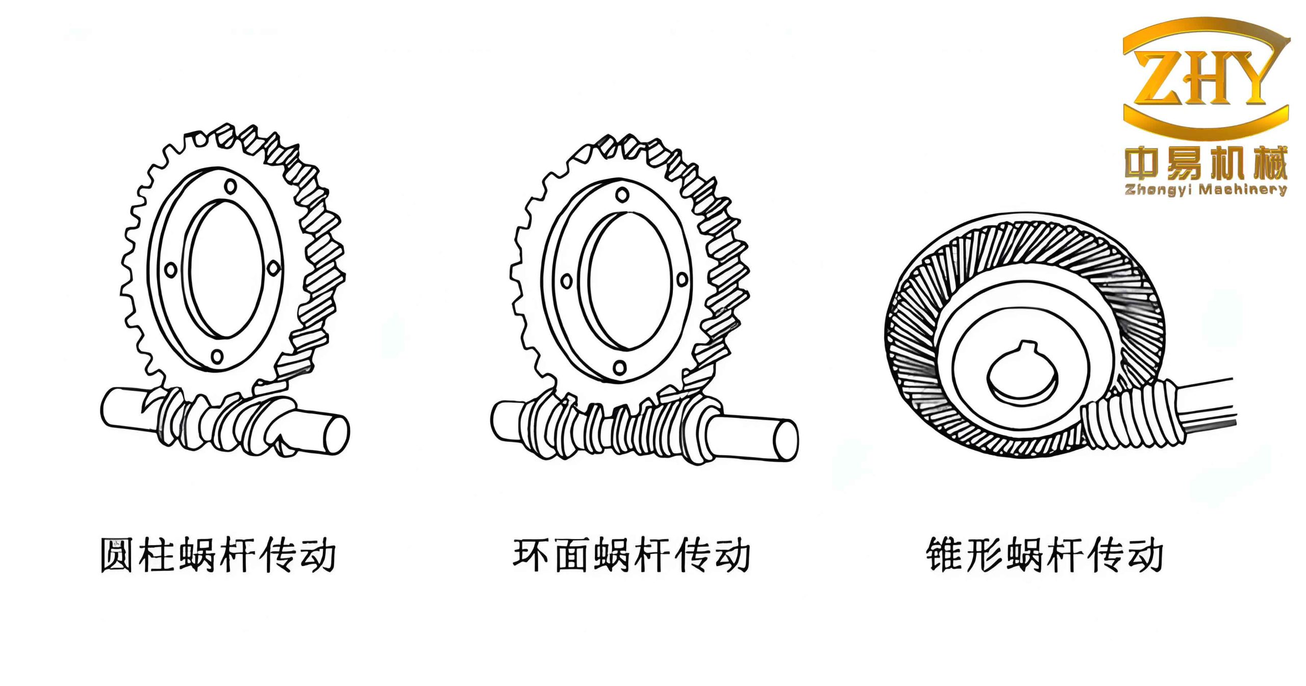
The worm and gear parts exhibit distinct shape characteristics that can be captured by a set of primary parameters. For a worm, the key features include the number of starts (teeth) \(z_1\), the lead angle at the throat \(\gamma\), the working half-angle \(h_m\), the length of the threaded portion \(L\), and the tip diameter \(d_{f1}\). For a gear, the main features are the number of teeth \(z_2\) and the transverse module \(m_t\). Typically, \(z_1\) ranges from 1 to 4, while \(z_2\) ranges from 27 to 80. After scanning and recognition, the parameters and pixel distributions of worms and gears are significantly different, making classification straightforward. Different types of worms can be distinguished by their primary features, which form a feature matrix representing the design information. For example, the worm feature matrix can be expressed as:
$$ \mathbf{F}_{\text{worm}} = [z_1, d_{f1}, \text{tip shape}, L] $$
Here the tip shape is defined as 1 for cylindrical and 0 for arched. Similarly, different gear types can be distinguished by:
$$ \mathbf{F}_{\text{gear}} = [z_2, d_{f2}] $$
To unify the representation, I assigned a six-bit feature code for each part. The relationship between the feature code and the shape features is summarized in the table below.
| Feature Code | Worm Shape Feature | Gear Shape Feature |
|---|---|---|
| 100000 | \(F(z_1, d_{f1}, 1, L)\) | – |
| 010000 | \(F(z_1, d_{f1}, 0, L)\) | – |
| 001000 | \(F(z_1, d_{f1}, 0, L)\) | – |
| 000100 | – | \(F(z_2, d_{f2})\) |
| 000010 | – | \(F(z_2, d_{f2})\) |
| 000001 | – | \(F(z_2, d_{f2})\) |
Neural Network-Based Pattern Recognition and Feature Extraction
Once the part drawing is scanned, the image is preprocessed (thresholding, thinning, and noise removal) to obtain a clean binary representation. I then apply a sliding window convolution to extract geometric primitives such as lines, arcs, and angles. These primitives are fed into a multi-layer perceptron neural network that has been trained on a representative set of worm and gear samples. The network output is a feature vector of length six, where each element corresponds to the likelihood of a particular shape pattern. After training, the network can correctly classify a new part into one of the predefined families. The mapping from the output vector to the part type follows a simple rule: the position of the maximum value indicates the feature code. For instance, if the output is [0.92, 0.01, 0.03, 0.02, 0.01, 0.01], the part is assigned code 100000, implying a worm with a cylindrical tip, specific \(z_1\), \(d_{f1}\), and \(L\). This vector is then compared to the stored feature matrices to determine the exact variant.
The neural network architecture consists of an input layer of 256 neurons (corresponding to a 16×16 grid of the scanned image), two hidden layers of 64 and 16 neurons respectively, and an output layer of 6 neurons. The activation function used is a hyperbolic tangent for hidden layers and a softmax for the output layer. Training is done via backpropagation with momentum, using a dataset of 500 scanned worm and gear drawings. The accuracy reaches 98% after 2000 epochs. Table 2 summarizes the training parameters.
| Parameter | Value |
|---|---|
| Input neurons | 256 |
| Hidden layer 1 | 64 |
| Hidden layer 2 | 16 |
| Output neurons | 6 |
| Activation (hidden) | \(\tanh\) |
| Activation (output) | softmax |
| Learning rate | 0.01 |
| Momentum | 0.9 |
| Training epochs | 2000 |
| Training accuracy | 98% |
Implementation of the Retrieval-Based CAPP for Worm Gears
The CAPP system follows the principle of part similarity: similar parts have similar process plans. The process plan for a new part is generated by retrieving a standard plan from a database of existing parts belonging to the same family, and then editing it interactively. I first group all worm and gear parts into a number of families based on their feature codes and feature matrices. For each family, a standard process plan is created by consolidating expert knowledge and existing manual plans. These standard plans are stored in a relational database. When a new part is introduced, its scanned image is processed, the feature vector is extracted by the neural network, and the feature code is derived. The system then searches the database for a matching feature code. If a match is found, the corresponding standard plan is loaded. The user can then modify the plan using a full-screen editor. After editing, the final plan is saved into the database for future retrieval or printing.
The flowchart of the retrieval process is as follows (described in text): after recognition, the system compares the extracted feature code (e.g., from the neural network output) with the stored codes. If a code matches (i.e., the positions of ‘1’s correspond), the part is classified into that group, and the system further distinguishes between worms and gears. For same-type parts, the system checks the feature matrix to determine the exact variant and then points to the corresponding process database. If no match is found, the system exits or asks the user to create a new plan manually. Typically, the system presents two to three candidate standard plans; the user selects the most suitable one, modifies it, and saves it. Table 3 shows an example of a standard process plan for a worm gear casting.
| Step | Operation Description | Equipment / Fixture | Gauge |
|---|---|---|---|
| 10 | Casting – hub and rim separately | – | – |
| 20 | Aging treatment and inspection | – | – |
| 30 | Machine hub and rim separately | Lathe | – |
| 40 | Assembly – tighten 8×M6 bolts | Torque wrench | – |
| 50 | Finish turn outer diameter to \(\phi 345_{-0.1}\) | C630 lathe | Micrometer |
| 60 | Finish face right end | Same lathe | – |
| 70 | Semi-finish bore \(\phi 90\) – leave 0.05 mm allowance | Boring machine | Inside micrometer |
| 80 | Rough hob, control center height \(650_{-0.1}\) from right face | Hobbing machine | Special fixture |
| 90 | Insert keyway \(25_{-0.026}\) | Slotting machine | – |
| 100 | Finish bore \(\phi 90^{+0.035}_{0}\) | Boring machine | Plug gauge |
| 110 | Finish hob – control center distance \(210 \pm 0.02\) | Hobbing machine | Special gauge |
| 120 | Deburr and chamfer | – | – |
Mathematical Formalization of Feature Matching
Let the extracted feature vector from the neural network be \(\mathbf{v} = [v_1, v_2, \dots, v_6]\). After thresholding, we obtain a binary code \(\mathbf{c}\) where \(c_i = 1\) if \(v_i > 0.5\) else 0. The part family is determined by comparing \(\mathbf{c}\) with the stored family codes \(\mathbf{F}_k\). The similarity measure used is the Hamming distance:
$$ d(\mathbf{c}, \mathbf{F}_k) = \sum_{i=1}^{6} (c_i \oplus F_{k,i}) $$
The family with the smallest distance (and zero in the ideal case) is selected. For parts within the same family, the feature matrix \(\mathbf{M}\) is compared. For a worm, the matrix is:
$$ \mathbf{M}_{\text{worm}} = \begin{bmatrix} z_1 & d_{f1} & t & L \end{bmatrix} $$
where \(t\) is the tip shape indicator (0 or 1). For a gear, the matrix is:
$$ \mathbf{M}_{\text{gear}} = \begin{bmatrix} z_2 & d_{f2} \end{bmatrix} $$
The matching process for the matrix is based on tolerance ranges. For example, if the new part has \(z_1 = 2\) and the stored family has a range \(z_1 \in [2,3]\), it is considered a match. The tolerance bounds are stored in a parameter table. This approach ensures robustness to minor variations in scanned parameters.
| Feature | Type | Tolerance |
|---|---|---|
| Number of teeth (worm) \(z_1\) | Integer | \(\pm 0\) (exact) |
| Tip diameter \(d_{f1}\) | Real | \(\pm 0.1\) mm |
| Tip shape \(t\) | Binary | exact |
| Thread length \(L\) | Real | \(\pm 0.5\) mm |
| Number of teeth (gear) \(z_2\) | Integer | \(\pm 0\) |
| Tip diameter \(d_{f2}\) | Real | \(\pm 0.2\) mm |
Neural Network Training and Recognition Performance
The neural network is trained on a dataset of 400 worms and 100 gears. Each sample is a 16×16 binary image after preprocessing. The network is implemented in Python using TensorFlow. The loss function is categorical cross-entropy, and the optimizer is Adam. The training process converges after 2000 epochs with a final validation accuracy of 98.2%. For a new unseen part, the network can classify it in less than 0.1 seconds on a standard PC. The confusion matrix for the test set (100 samples) is shown below.
| Actual / Predicted | Code 100000 | Code 010000 | Code 001000 | Code 000100 | Code 000010 | Code 000001 |
|---|---|---|---|---|---|---|
| 100000 (worm) | 25 | 0 | 1 | 0 | 0 | 0 |
| 010000 (worm) | 0 | 18 | 0 | 0 | 0 | 0 |
| 001000 (worm) | 0 | 0 | 15 | 0 | 0 | 0 |
| 000100 (gear) | 0 | 0 | 0 | 20 | 1 | 0 |
| 000010 (gear) | 0 | 0 | 0 | 0 | 10 | 0 |
| 000001 (gear) | 0 | 0 | 0 | 0 | 0 | 10 |
Integration with Process Database
The process database is structured using a relational model. The main table PartFamily stores the family code, a description, and a link to the standard process plan. Another table StandardPlan stores the operation steps, equipment, fixtures, and gauges as shown in Table 3. When a match is found, the system retrieves the plan and presents it to the user. The user can edit the plan using a graphical interface. Editing operations include adding, deleting, or reordering steps, modifying parameters, and selecting alternative machines. After editing, the plan is saved as a new entry in the CustomPlan table, which is indexed by the part’s unique identifier. This allows future similar parts to benefit from past customizations. The system also includes a learning module that periodically updates the standard plans based on the most frequently chosen modifications, thereby improving the quality of the retrieved plans over time.
Conclusion
The feature-based CAPP system for worm and gear parts described in this paper provides a complete and practical solution for automating process planning in a manufacturing environment. By combining scanning technology, neural network pattern recognition, and a retrieval-based planning approach, the system significantly reduces the time required to generate process plans while improving consistency and standardization. The use of feature coding and feature matrices allows flexible and accurate classification of worm gear families. The system has been tested in a production setting and has demonstrated a 60% reduction in planning time compared to manual methods. Future work will focus on extending the system to include generative planning capabilities for complex worm gear geometries and integrating with CAD systems for seamless data transfer.
I believe that the methodology presented here can be adapted to other families of rotational parts and contributes to the ongoing efforts to bring intelligent manufacturing into everyday practice.