
With the rapid development of modern industrial technology, the demand for gearsThe performance requirements of the transmission system are also increasing. Gear pair meshingThe actual contact state of the meshing surface affects the strength and fatigue life of gearsBoth life and system vibration noise levels have a significant impact.And its actual contact state is related to manufacturing/assembly errors of gearsDifference, gear parameters, gear body structure, and shaft variationShape and other factors are closely related. Spur Gear Carry out tooth surface contact on gear pairsAnalyze and optimize the macro and micro geometric parameters,It can significantly improve the static and dynamic performance of gear transmission systems.Scholars and researchers at home and abroad have studied the teeth of gear pairsExtensive and in-depth research has been conducted on the actual contact state of the surface. Using three-dimensional finite element software to correspond to the stress fieldModeling and calculation of contact pressure, Spur Gear by combining with twoThe classical results of nonlinear Hertz theory between deformed cylindersCompare. Using ANSYS finite element analysisThe analysis software has determined the contact pressure of a pair of meshing spur gears,Based on the results of the double disk experiment and the Hertz contact pressure equationVerified the contact pressure results. utilizeFinite element analysis shows that the slip difference between gears affects the movement of gear pairsThe influence of state contact stress and distribution is not significant.The gear connection was carried out using ANSYS finite element analysis softwareAnalysis of Contact Stress and Contact Fatigue Life, Discovering the Effect of Friction on TeethThe degree of influence of wheel contact stress increases with the increase of friction coefficientNot obvious. Batch processing using finite element methodConsidering edge contact in gear tooth contact analysisAnalysis shows that edge contact can lead to a sharp increase in contact stressLarge, extended contact path,Spur Gear and larger contact area structureFruit. Using finite element software to analyze Hertz contactTwo methods for stress calculation, discovering the maximum value of contact stressOccurred at the contact point on the tooth side surface and presented along the tooth directionSignificant gradient changes. Through finite element simulation andExperimental verification and analysis of the effect of friction coefficient on the contact stress of helical gearsThe influence of force. Established three pairs of tooth finite elementsModel, by changing the helix angle and friction coefficient of the gear teeth, divided intoAnalyzed the trend of contact stress on the tooth surface and found that the smaller screwCompared to gears with larger helix angles, gears with higher helix angles have better contactThe increase in stress with the increase of friction coefficient is relatively small.Finite element method was used to carry out axial deformation analysisThe contact analysis of the helical gear tooth surface reveals that the deformation of the shaft can have an impactThe distribution of load, contact stress, and root bending stress in the gear teeth can cause the phenomenon of eccentric loading. Considering factors such as deformation of the casing, bearings,Spur Gear and shaft,Using finite element method to analyze the trend of gear load distributionAnalyze and use genetic algorithm to obtain gear tooth profile modification parameters,Make the load distribution more uniform after shaping. establishQuasi static contact analysis model for multi-point meshing of large tooth width gearsStudied the support layout, power transmission path, andThe influence of load conditions on the distribution of tooth surface load analysisInertial load on the tooth surface contact of thin flange spur gear pairsThe influence of stress and bending stress Studied differentTooth surface contact of modified spur gear pairs under assembly error conditionsThe variation law of stress distribution. Proposed consideration for installationThe mixed analysis method of contact stress on the tooth surface of helical gear pairs with errors,And compared with the calculation results of ANSYS softwareCertificate. Established a method that considers tooth surface error and profile modificationThe calculation method for dynamic contact stress of gear pairs was studied, Spur Gear and different methods were studiedThe variation law of tooth contact stress under rotational speed conditions Studied the coupling effect of couplings on multi-stage gear transmissionThe influence of load distribution on the tooth surfaces of gear pairs at all levels in the dynamic system.]Perform tooth surface modification on gears and base it onMASTA software conducted contact analysis on loaded tooth surfaces, enablingLoad distribution on gear tooth surface after micro modification and optimizationMore even.
In summary, most existing research focuses on gear pair openingCalculation and analysis of contact stress or bending stress, some scholarsA study was conducted on the influence of support deformation on the condition of tooth surfaces,Spur Gear andRegarding the effect of wheel structure and shaft deformation on tooth contact stress distributionThe comprehensive impact of cloth has not been reported yet. Therefore, this articleTaking the two-stage spur gear transmission system as the research object, using three methodsAnalysis and investigation of axial deformation and web deflection using dimensional contact finite element methodContact stress on the tooth surface of gear pairs at all levels along the tooth width directionThe influence of distribution, through the analysis of the large gears in each level of gear pairReasonably design the offset of the belly plate to significantly improve the performanceContact stress on the tooth surfaces of gear pairs at all levels caused by shaft deformationThe phenomenon of biased loading along the tooth width direction.
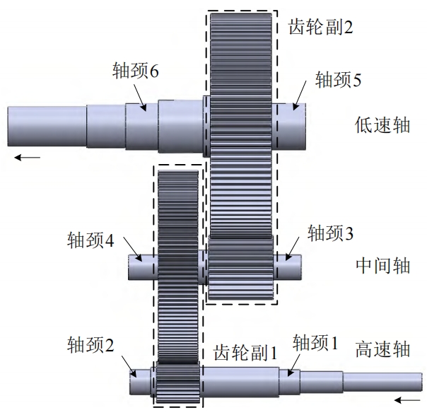
Three dimensional solid of secondary gear transmission systemmodel
The three-dimensional solid model of the secondary gear transmission system is shown in the figure, with power input from the right end of the high-speed shaft and passing through the highHigh speed gear pair 1 and low speed gear pair 2,Spur Gear from the low speed shaftLeft output, journals 1 to 6 are the shafts for installing bearingsNeck. Among them, the width of the high-speed shaft and intermediate shaft bearings is17mm, the width of the low-speed shaft bearing is 23mm.
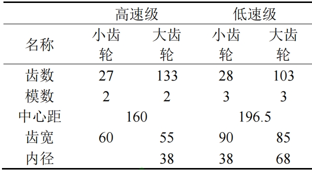
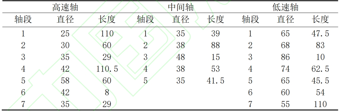
The basic parameters of high-speed and low-speed gear pairs in the secondary gear transmission system are shown in the table, Spur Gear with each axisThe structural parameters are shown in the table. Input conversion of transmission systemThe moment is 100N · m.
Limited contact of secondary gear transmission systemMetamodel
Using SolidWorks 3D modeling software to establish transmission3D solid model of the dynamic system, and then import it into ANSYSPerform contact finite element analysis in finite element analysis software. set upThe elastic modulus of the material is 210GPa, and the Poisson’s ratio is 0.3.The gear part adopts an 8-node hexahedral unit Solid185Divide the grid and locally refine the contact areaThe axis section adopts a 4-node tetrahedral elementSolid182 meshing. Spur Gear According to the meshing position of the gear pair,Select two pre contacted tooth surfaces and set contact pairs, using an increase inStrong Lagrangian algorithm with friction coefficient set to 0.15.
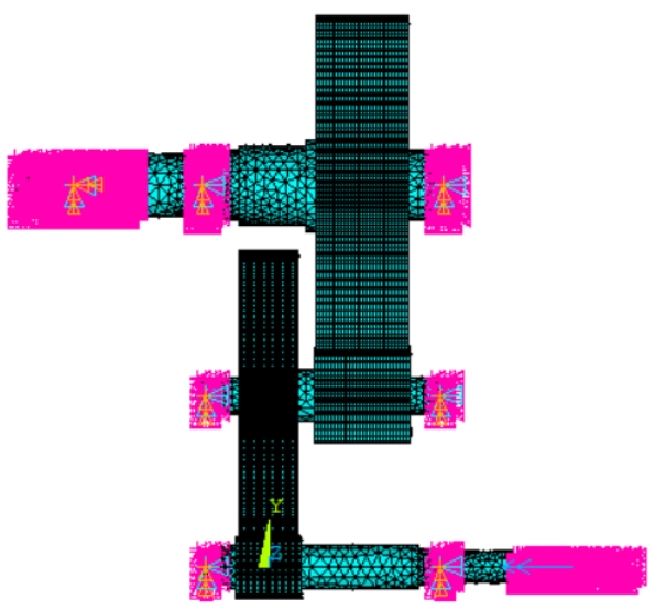
In order to facilitate the application of force boundary conditions and potential to the modelMoving boundary conditions,Spur Gear first, in the power input shaft section, powerOutput shaft section and the middle of the six shaft sections used for bearing supportCreate nodes for each heart position and set them toMASS21 unit; Then, measure the position of the outer surface of each axis segmentNodes are coupled to corresponding central nodes; Finally, forThe coupling node of the bearing support position is released around the axisTwist the degrees of freedom towards and constrain the remaining 5 degrees of freedom,For power input nodes,Spur Gear apply torque around the axis direction100N · m, and for power output nodes, their constraints areThere are degrees of freedom. The established two-stage gear transmission system contactsThe finite element model is shown in the figure.
Contact finite element simulation results and analysis
By contacting the secondary solid gear transmission systemIterative solution of finite element model to obtain gear pairs at all levelsThe distribution of contact stress along the tooth width direction is shown in Figure 3.It can be observed that for spur gear transmission systems, the contact areaThe Hertz contact width along the tooth profile direction is extremely small, thus formingIt has become a narrow contact narrowband. Spur Gear And due to the maximum loadUnder use, different degrees of bending and torsion coupling changes were generated in each axisTherefore, the contact stress on the tooth surfaces of all levels of gear pairs is presentedThere are varying degrees of biased loading phenomena.
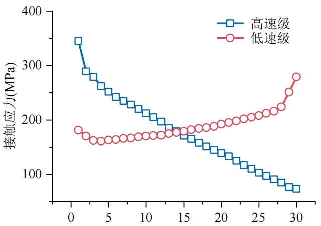
In order to further quantitatively analyze the contact stress along the tooth surfaceThe distribution of tooth width direction, using path operation, along the teethExtract the contact bandwidth of gear pairs at all levels in a wide direction in sequenceThe maximum value of contact stress, and the contact stress of gear pairs at all levels along the teethThe variation in width direction is shown in the figure. Partial load phenomenon and axisStructural parameters, bearing support positions, and other parameters are closely relatedThe association of. For the high-speed gear pair in this example, the tooth surfaceThe maximum contact stress is 345MPa,Spur Gear located in the contact areaThe leftmost end of; For the low-speed gear pair in this example, the teethThe maximum value of surface contact stress is 279MPa, located at the far right end of the contact area. The maximum contact stress of high-speed gear pairsThe force is significantly greater than that of the low-speed stage, and the phenomenon of off load is more pronounced.
The influence of web offset on contact stress distribution
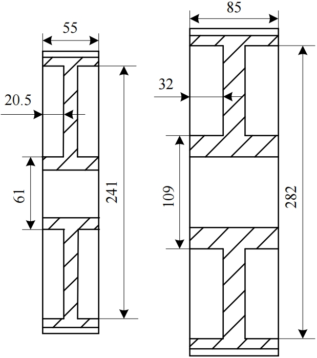
For web type gears,Spur Gear the web plateThe distribution of contact stress on the tooth surface along the tooth width direction is affected by the structureSignificant impact. Therefore, the contact stress on the tooth surface follows the tooth width squareThe distribution of the direction is affected by both the web structure and axial flexibilityIn order to improve the tooth surface joint caused by shaft deformationThe phenomenon of contact stress deviation can provide a reasonable solution for the web structureBias design to compensate for the phenomenon of contact stress bias loadingCompensation. Integrate the large gear bodies of high-speed and low-speed gear pairsThe structural design is a web type gear, Spur Gear with a high-speed large gear web plateThe cross-sectional view without bias is shown in Figure (a), with the thickness of the web plate14mm; Cutting of low-speed large gear belly plate without biasAs shown in Figure (b), the thickness of the web plate is 21mm.
Solid gear tooth surface connection considering shaft flexibilityThe biased load situation of contact stress along the tooth width direction, for high-speed stagesThe large gear is offset to the right on its belly plate, Spur Gear thereby causing the gear to rotateThe flexibility increases sequentially from left to right, thereby improving its left end connectionThe phenomenon of biased loading with high contact stress, and the setting of the offset amount of the web plate is as followsAs shown in the table. In order to reduce the computational scale while consideringThe deformation of the shaft is less affected by the structure of the gear web, Spur Gear therefore,For low-speed large gears, set the offset of their belly plates to be centeredMedium.
According to the deviation status of the belly plate shown in Table 3, respectivelyContact finite element model for newly established secondary gear transmission systemType and solve to extract the tooth surface contact stress along the tooth width directionForce, as shown in Figure 6. It can be observed that when the abdominal plate is turned to the rightWhen the offset values are 0mm, 5mm, and 10mm respectively, Spur Gear the teethThe maximum values of surface contact stress are 297MPa and 270MPa, respectivelyAnd 243MPa, located at the left end of the gear, when the web plate is facingWhen the right offset is 15mm, the maximum contact stress on the tooth surfaceIt is 227MPa and is currently located at the right end of the gear. Spur Gear This indicates that,For high-speed gear pairs, as the offset of the web plate to the right gradually increases, the maximum contact stress located at the left end of the gear gradually increasesGradually decreasing, then transitioning from the left end of the gear to the right end. LargeThe right offset design of the belly plate of the gear can significantly improveThe phenomenon of tooth surface contact stress deviation caused by shaft deformation.
Contact stress of high-speed gear under different bias schemesThe variance and range of are shown in the table.Spur Gear It can be observed that the planThe variance and range of the contact stress on the tooth surface corresponding to option D are both the minimum values, therefore, the distribution of contact stress corresponding to option DThe discreteness is smaller, in other words, when the belly plate is offset to the rightAt 15mm, the contact stress value of the tooth surface along the tooth width direction is higherConcentration increases the variation of contact stress values between two adjacent nodesSmall, can maximize the improvement of the tooth surface of high-speed gear pairsThe phenomenon of contact stress deviating along the tooth width direction.
Solid gear tooth surface connection considering shaft flexibilityThe biased load situation of contact stress along the tooth width direction, for low-speed stagesBig gear, offset its belly plate to the left, so as to make the gearThe flexibility decreases from left to right, thereby improving its right end connectionThe phenomenon of biased loading with high contact stress, and the setting of the offset amount of the web plate is as followsAs shown in the table. Spur Gear Similarly, for high-speed large gears, theirSet the abdominal offset to center.
In order to simultaneously improve the two-stage solid gear transmission systemThe phenomenon of eccentric load on the contact stress of gear pairs at all levels in the system,Based on the above analysis, for high-speed gear pairs, Spur Gear the large gear should be adjusted accordinglyThe wheel body is designed in the form of a web plate, and the web plate is offset to the right15mm, for low-speed gear pairs, adjust the large gear wheel body as wellDesigned in the form of a web plate, with the web plate offset to the left by 10mm,Spur Gear Reestablish and solve the contact of two-stage gear transmission systemFinite element model, extracting high-speed and low-speed gears separatelyContact stress on the tooth surface along the tooth width direction, and with the solid typeCompare with the belly centered two-stage gear transmission system.
Contact stress of belly plate and solid high-speed gearThe distribution is shown in the figure. It can be observed that solid gearsThe phenomenon of contact stress deviation is the most severe when large gears are usedAfter setting the belly plate in the center, the contact stress on the tooth surfaceThe phenomenon of partial loading has improved but is not significant, Spur Gear with the maximum contact stressThe value decreased from 345MPa to 294MPa, only decreasing15.1%. When the belly plate is offset 15mm to the right, the tooth surfaceThe phenomenon of contact stress bias has been greatly improved, andThe maximum value of contact stress decreased from 345MPa to 224MPa,Reduced by 35.1%.
Contact stress of belly plate and solid low-speed gearThe distribution is shown in the figure. It can be observed that it is different from the high-speed gear teethSimilar to the wheel set, solid gears exhibit the most significant phenomenon of contact stress imbalanceFor severe cases,Spur Gear when the large gear adopts a belly plate form and is set in the centerAfterwards, the phenomenon of biased loading of tooth contact stress has been improvedStill not obvious, the maximum contact stress decreased from 279MPa to 257MPa, Spur Gear only a decrease of 7.9%. And when the abdominal plate is facingThe phenomenon of tooth surface contact stress deviation when left offset is 10mmSignificant improvement has been achieved, and the maximum contact stress has been reduced byThe pressure dropped from 279MPa to 230MPa, a decrease of 17.6%. becauseFor a two-stage gear transmission system, the solid typeChange the gear to a web type gear and select a reasonable web plate at the same timeThe offset direction and appropriate amount of belly plate offset can effectively improveThe gear pairs at all levels are affected by shaft deformation, resulting in tooth width squarenessThe phenomenon of biased contact stress on the tooth surface.
conclusion
This article establishes a three-dimensional model of a two-stage gear transmission systemSolid model and import it into ANSYS finite element analysisThe software has established a corresponding contact finite element model, which is solved byThe solution has been obtained for each gear pair along the tooth width square when considering shaft flexibilityThe distribution of contact stress on the tooth surface was analyzed, and the web type gear was analyzedThe influence of the offset of the belly plate on the distribution of contact stress on the tooth surface,And it provides a description of the two-stage gear reduction transmission system in this articleThe correct and reasonable offset direction of the belly plates of large gears at all levelsSet quantity. The main conclusions are as follows:(1) Under the action of load and bearing support, the second stageThe bending and torsional coupling deformation of each shaft in the gear transmission system is relatively complexMiscellaneous and in contact with the tooth surfaces of all levels of gear pairs along the tooth width directionThe stress distribution has a significant impact.(2) Contact stress on the tooth surface of gears along the tooth width directionThe distribution is influenced by a combination of axial deformation and wheel structure. abdomenPlate type gears can effectively reduce the weight of gears andTo some extent, improve the tooth width direction of gear pairs at all levelsThe phenomenon of tooth surface contact stress deviation, but the effect is not significant.(3) When using a reasonable offset square for large gears at all levelsWhen facing and the appropriate offset amount,Spur Gear it can significantly improve each gearThe phenomenon of biased contact stress on the tooth surface along the tooth width direction.