
By conducting transient dynamic analysis on highly modified cylindrical spur gears and verifying the strength of spur gear meshing transmission, the dynamic characteristics of the mechanism can be understood. In order to better understand the dynamic characteristics of highly modified cylindrical spur gears, this article first converts the “. prt” format of the 3D model of spur gears created in UG (CAD) to the “. step” format, and then directly imports it into AnsysWorkbench for transient dynamic analysis and simulation.
1.Material assignment
The material of both the spur gear pinion and wheel wheels is designated as structural steel, with a density of 7850kg/m ^ 3, an elastic modulus of 2E+11Pa, and a Poisson’s ratio of 0.3.
2.Grid division
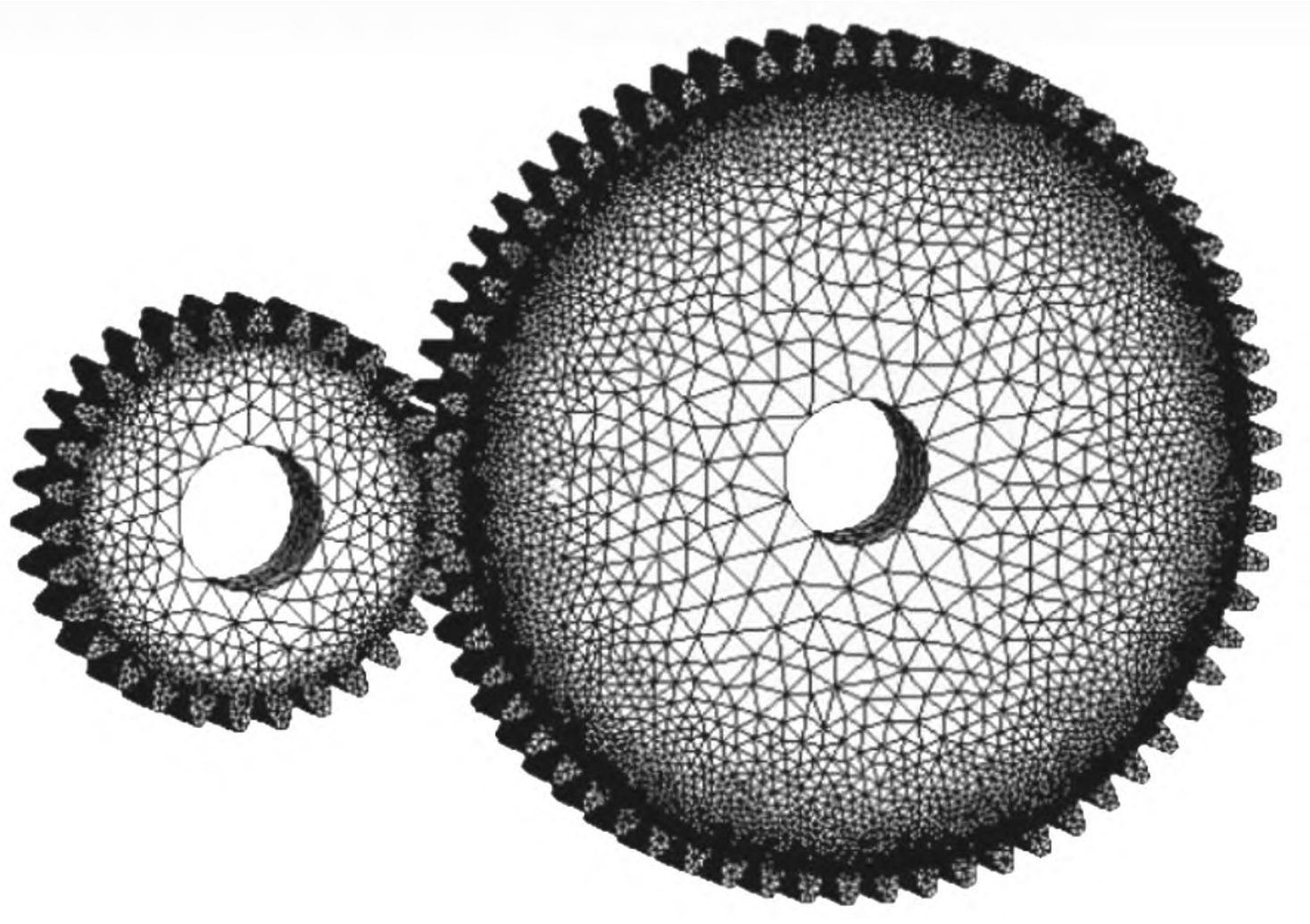
Use a 3D tetrahedral mesh to mesh the two spur gears. The more grids there are, the better the quality of the analysis, but it also increases the analysis time. Considering that the main focus is on the stress situation of the meshing teeth, the contact area of the spur gear is encrypted with a thickness of 2mm. After dividing the grid, a total of 1175893 nodes and 825316 units are generated, as shown in Figure 1.
3.Apply boundaries and loads
Apply boundary conditions and loads in the finite element environment. The spur gear pinion wheel is the driving wheel and the spur gear wheel is the driven wheel. Therefore, in setting the contact body, the spur gear pinion is selected as the contact geometry, the spur gear wheel is the target geometry, the contact type is friction contact, and the contact coefficient is set to 0.15. Then create constraints, manually create contact surfaces, and create 2 rotation pairs, all rotating around the Z-axis. Finally, add a load, add a rotation speed of 1 rad/s to the spur gear pinion, and add a torque load of 500N/m to the spur gear wheel, in the same direction as the spur gear pinion. Set the definition basis in load step control as sub steps, with the minimum sub step set to 20 and the maximum sub step set to 200, to conduct transient dynamic analysis on highly modified cylindrical spur gears.
4.Simulation results
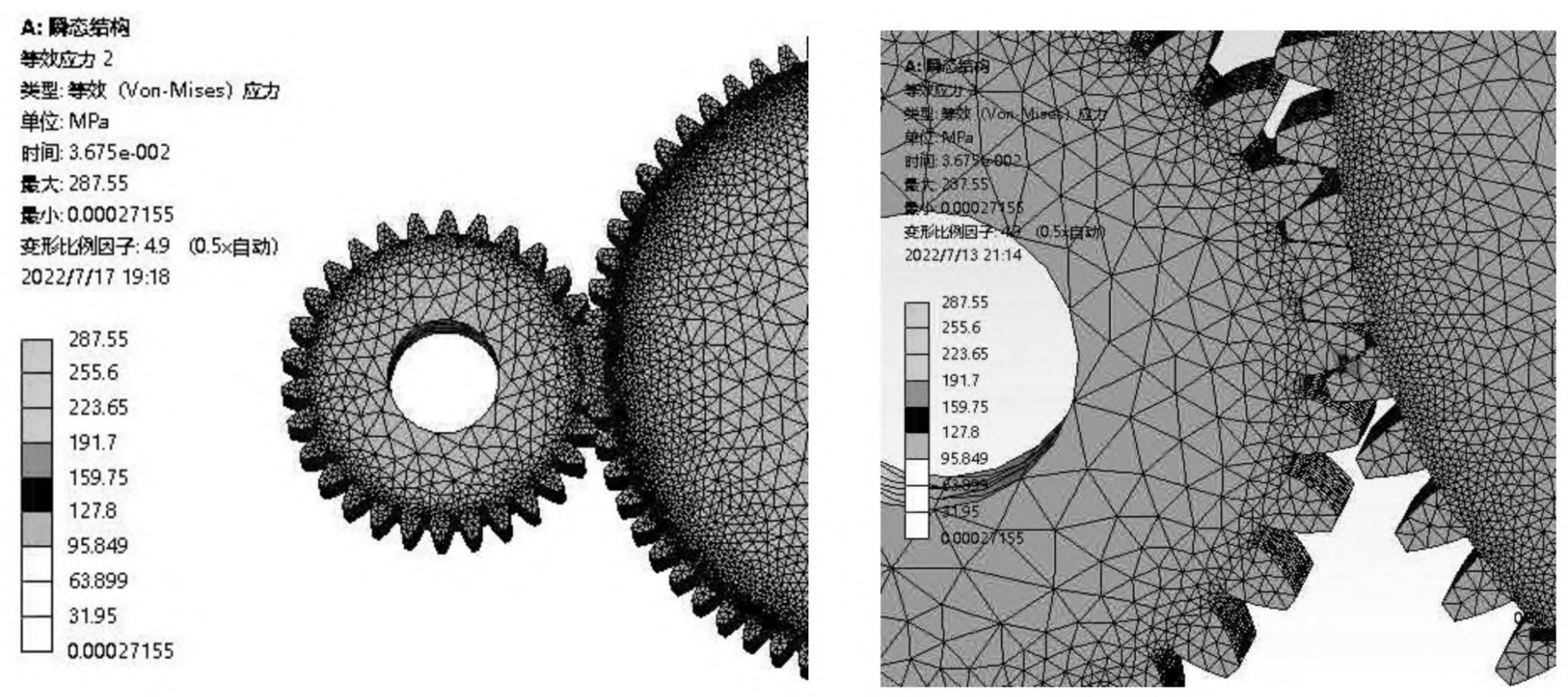
The transient analysis results of highly modified cylindrical spur gears are shown in Figures 2 and 3.

From the analysis results, it can be seen that the maximum contact stress of the two spur gears simulated is 287.55Mpa, located on the contact surface of the two tooth surfaces. The theoretical value of the maximum contact stress of the two spur gears calculated from the above Hertz formula is 283.367Mpa. Comparing the theoretical value with the simulation value, the error is relatively small and meets the requirements of the working conditions.