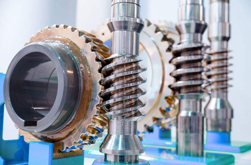
Finite Element Analysis (FEA) is a powerful computational tool used to evaluate the stress distribution in worm gear mechanisms. This method helps engineers understand the behavior of worm gear system under various loading conditions, identify potential failure points, and optimize the design for improved performance and durability. Here is a detailed overview of the process:

Steps in Finite Element Analysis of Worm Gear
- Geometry Creation and Meshing
- Geometry Creation: Create a detailed 3D model of the worm gear mechanism, including the worm and worm gear. This can be done using CAD software.
- Meshing: Discretize the geometry into finite elements (meshing). The quality and density of the mesh significantly affect the accuracy of the results. Finer mesh around critical areas (e.g., gear teeth) ensures more accurate stress analysis.
- Material Properties
- Define the material properties of the worm and worm gear, including Young’s modulus, Poisson’s ratio, yield strength, and other relevant parameters. Accurate material data is essential for realistic simulation results.
- Boundary Conditions and Loading
- Boundary Conditions: Apply appropriate boundary conditions to the model, such as fixed supports and constraints that simulate the actual mounting and operational conditions of worm gear.
- Loading Conditions: Apply the operational loads, including the torque, axial loads, and any other forces acting on the worm gear. These loads should reflect the real-world operating conditions worm gear will experience.
- Contact Definition
- Define the contact interactions between the worm and worm gear teeth. Accurate modeling of contact conditions, including friction coefficients and contact stiffness, is crucial for realistic stress analysis.
- Simulation
- Run the FEA simulation to solve for the stress distribution within the worm gear mechanism. This involves solving the equations of equilibrium, considering the applied loads, material properties, and boundary conditions.
- Post-Processing
- Analyze the results to identify stress concentrations, deformation patterns, and potential failure points. Key outputs include von Mises stress, principal stresses, and displacement fields.
Key Areas of Analysis
- Tooth Root Stress
- Analyze the stress concentration at the root of worm gear teeth, as this is a common location for fatigue failure due to cyclic loading.
- Surface Contact Stress
- Evaluate the contact stress between the worm and worm gear teeth. High contact stress can lead to pitting, wear, and surface fatigue.
- Overall Stress Distribution
- Assess the overall stress distribution in the worm gear mechanism to identify any unexpected stress concentrations or areas of concern.
- Deformation and Displacement
- Examine the deformation and displacement of worm gear components under load to ensure they remain within acceptable limits and do not interfere with the operation.
Benefits of FEA in Worm Gear Design
- Design Optimization
- FEA helps optimize worm gear design by identifying areas where material can be added or removed to improve strength and reduce weight without compromising performance.
- Failure Prediction
- Predict potential failure points and modes, allowing for proactive design modifications to enhance reliability and durability.
- Improved Performance
- Ensure that the worm gear operates efficiently under the expected load conditions, reducing the risk of premature wear or failure.
- Cost Savings
- Reduce the need for physical prototypes and testing by validating designs through simulation, saving time and resources in the development process.
By following this process, engineers can effectively use FEA to analyze and improve the design of worm gear mechanisms, ensuring their reliability and performance in industrial applications.
