1. Fatigue analysis software FE Safe
Nowadays, the mainstream fatigue analysis software mainly includes the fatigue simulation software nCode produced by ANSYS in the United States, the fatigue analysis software HyperLife produced by Altair in the United States, the fatigue analysis software FE Safe developed by Dassult in France, and the fatigue analysis software MSC Fatigue produced by MSC in Switzerland. Among them, FE Safe is a powerful, comprehensive, and user-friendly fatigue analysis software that focuses on finite element models, and can also be integrated with the finite element analysis software ABAQUS. The simulation results obtained in ABAQUS can be directly input into FE Safe for fatigue analysis, and the results obtained from FE Safe fatigue analysis can also be directly input into ABAQUS for cloud map display through pre – and post processors. The stress calculation of the finite element model is carried out using ABAQUS software, which is suitable for fatigue analysis of single tooth meshing finite element models of helical gears with different modification coefficients in FE Safe.
2. Finite element fatigue analysis setup
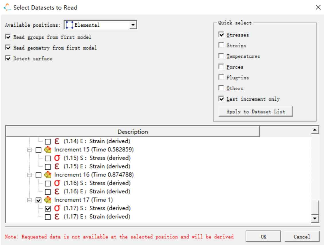
Import the output database odb file of ABAQUS static analysis into FE Safe, and FE Safe will automatically scan the odb file. Users can freely choose the load of the analysis process. In this chapter, the last incremental step data of the static analysis process is used as the load for fatigue analysis, and the selection window is shown in Figure 1.
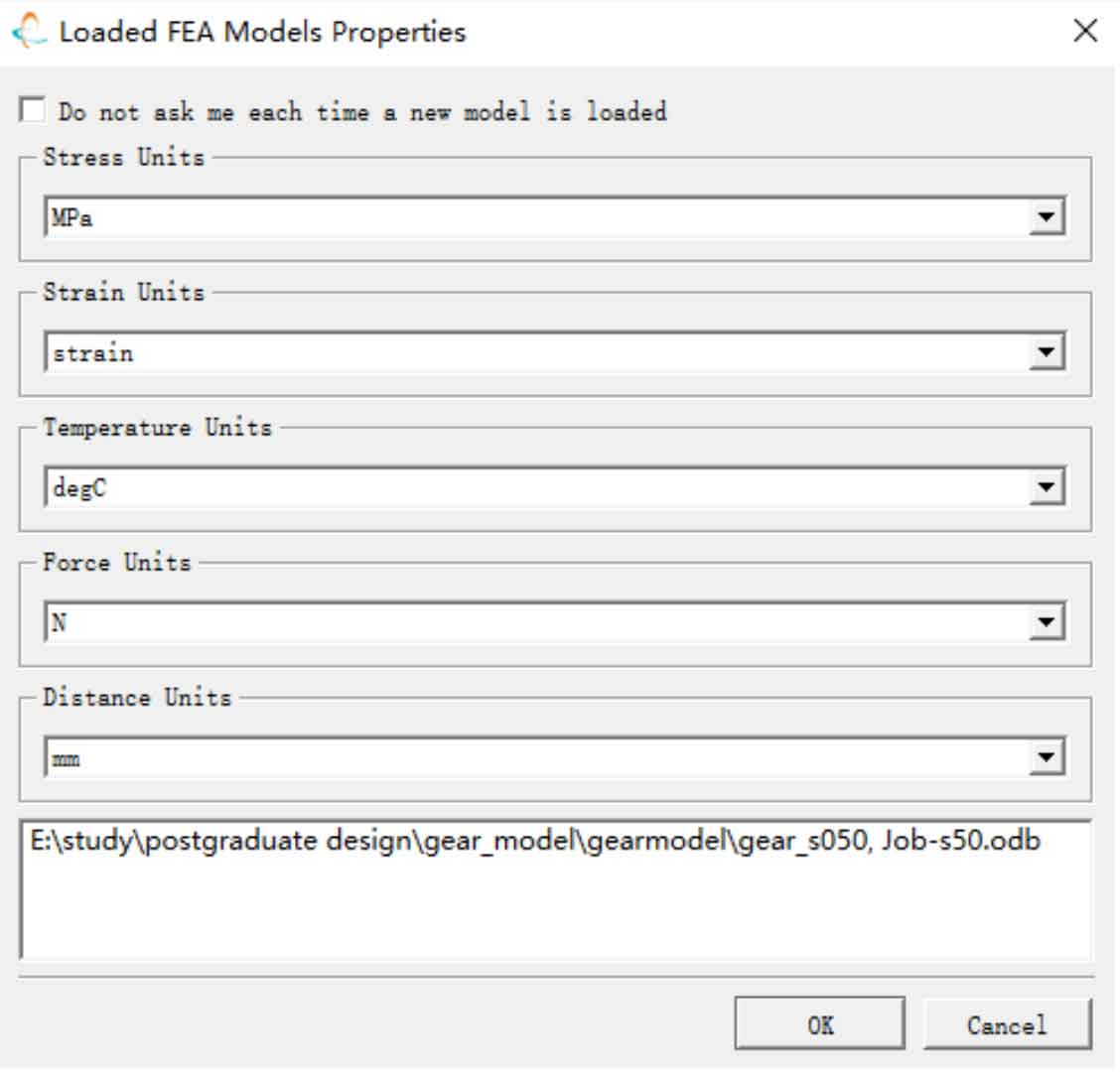
After importing the model, as the data in the ODB file has no units, a finite element model unit setting window will pop up in the FE Safe software to set the data units in the ODB model for subsequent fatigue analysis, as shown in Figure 2.
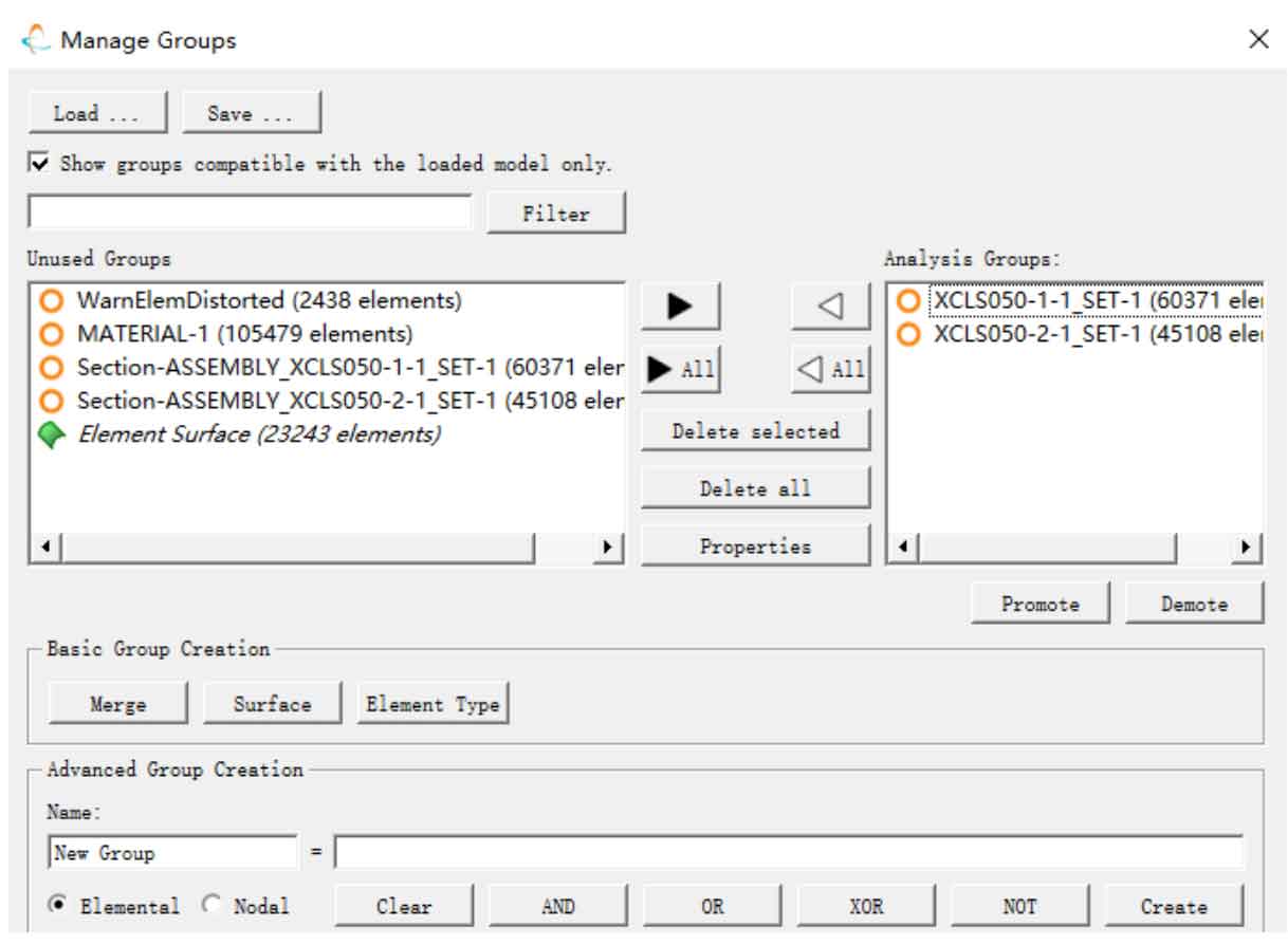
Next, select and group the units that need to be analyzed in the model, exclude the parts that do not need to be calculated, and retain the parts that need to be calculated. The grouping of units in FE Safe is shown in Figure 3.
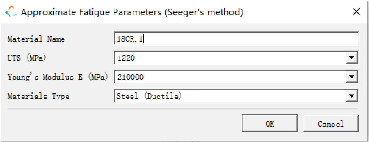
Next, add material properties to the material library, set the material name, material tensile strength of 1220MPa, material elastic modulus of 210000MPa, and material category of ductile steel as shown in Figure 4.
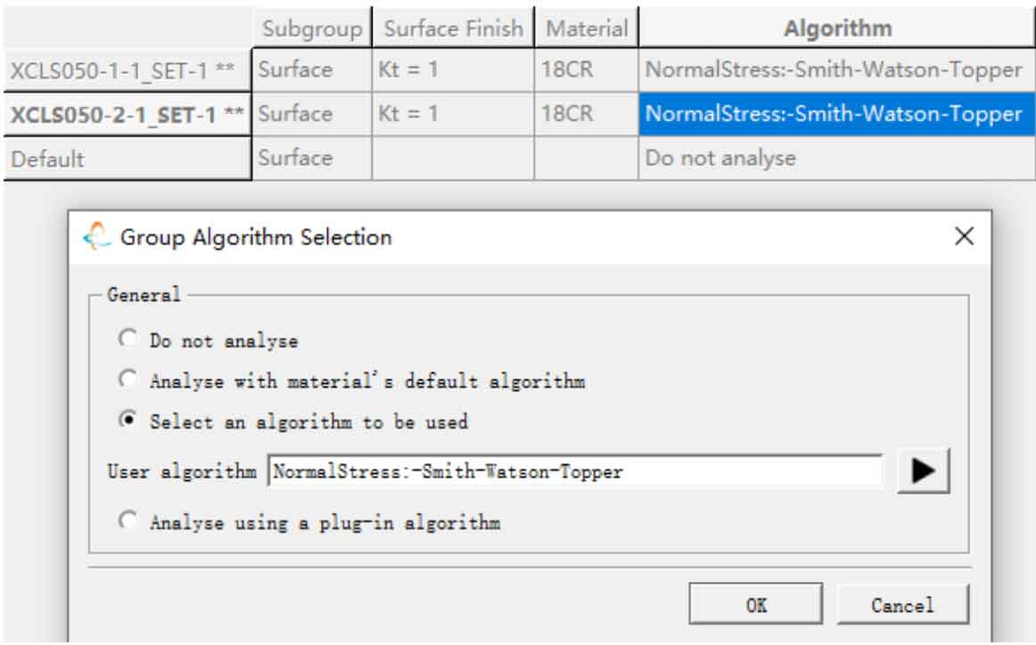
Set the material and fatigue algorithm for the single tooth finite element model of the wheel and pinion gears, and select the Smith Watson Topper method for stress correction, which is suitable for uniaxial high cycle fatigue and the loading mode of static finite element analysis in this chapter. The setting interface is shown in Figure 5, and the FE Safe setting is now completed.
3. Life analysis results of helical gears with different modification coefficients
According to the settings in Chapter 2, fatigue analysis of helical gears with different modification coefficients was conducted, and the analysis results are as follows.
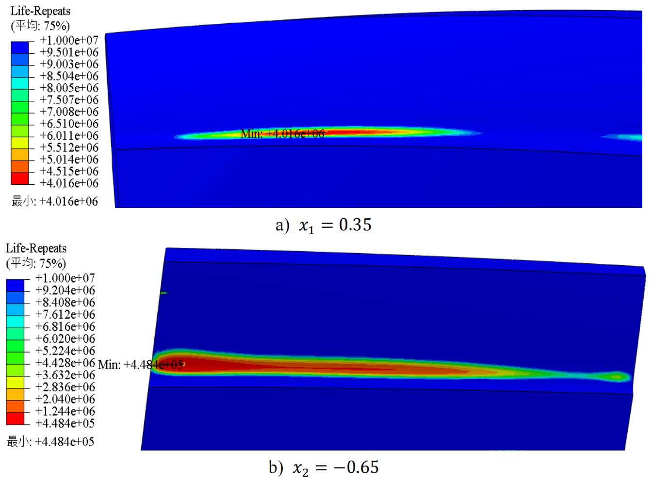
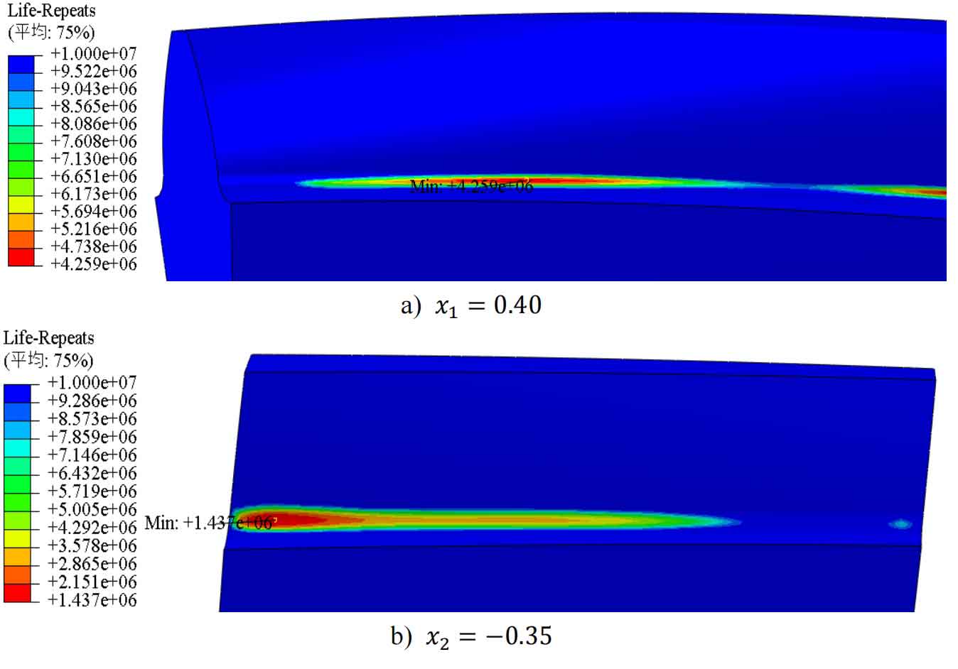
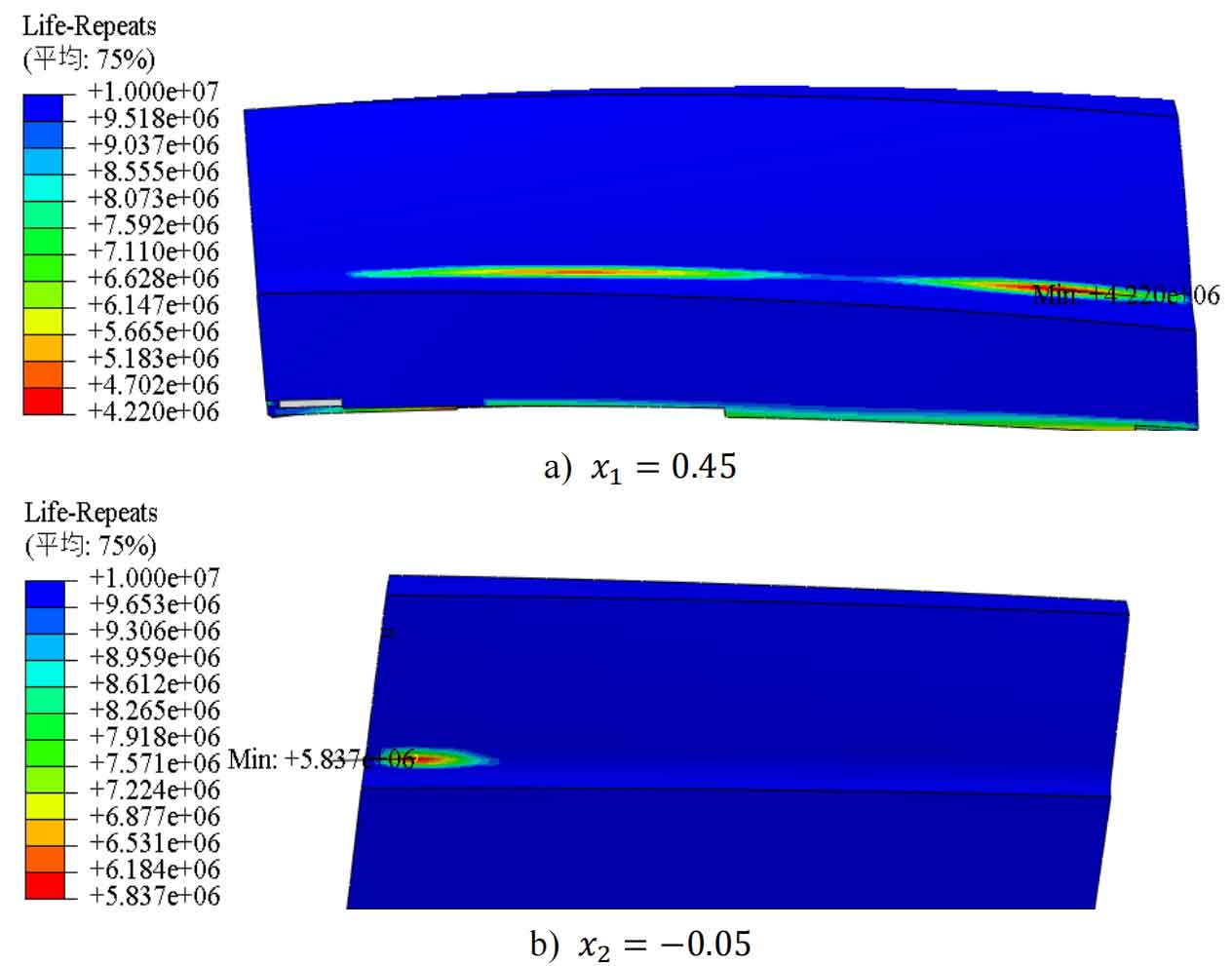
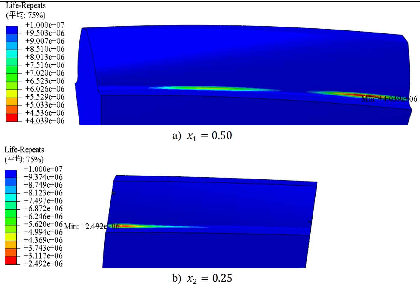
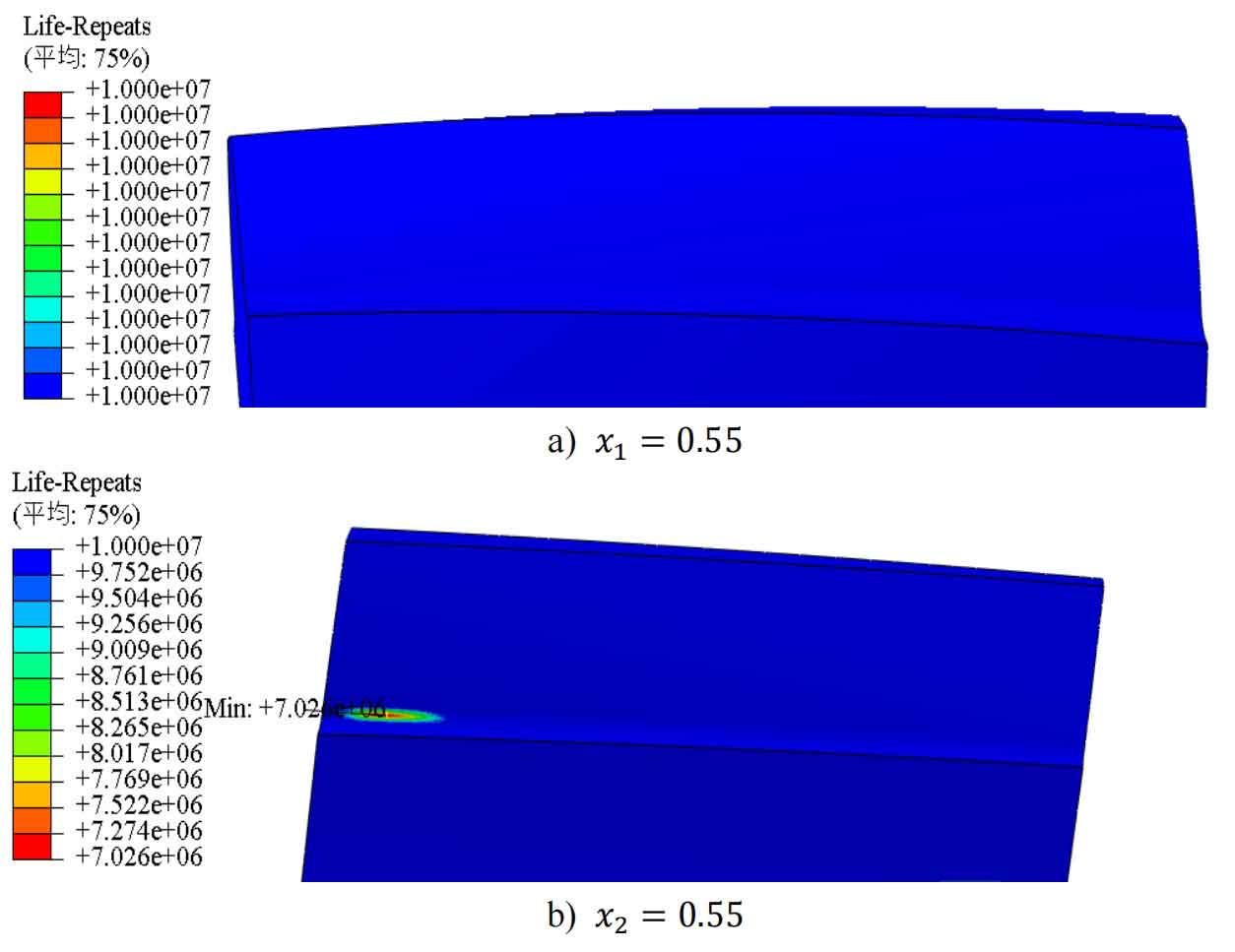
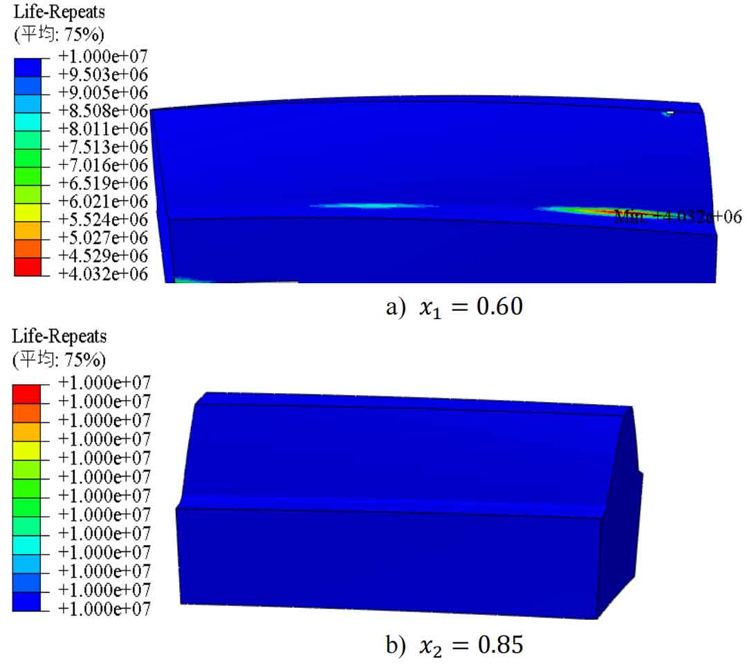
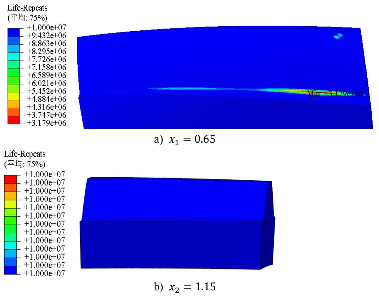
Based on the FE Safe single tooth meshing fatigue analysis results above, it can be seen that under the same subway operating conditions, when the deformation coefficient changes from pinion to wheel within the selected range, the bending fatigue life of the pinion gear will undergo two changes, first increasing to a certain value and then decreasing. The bending fatigue life of the wheel gear will first increase to a certain value, then decrease slightly to a certain value and then increase to 10 ^ 7. The minimum bending fatigue life of wheel and pinion gears is always at the tooth root position farthest from the meshing line to the tooth root. The bending fatigue life of the pinion gears in the helical gear pair with a modification coefficient of 𝑥 1=0.55 𝑥 2=0.55 reaches 10 ^ 7. The bending fatigue life of the wheel gear in the helical gear pair with a modification coefficient of 𝑥 1=0.60 𝑥 2=0.85 and 𝑥 1=0.65 𝑥 2=1.15 reaches 10 ^ 7.
