
The stiffness calculation of spiral bevel gear requires the comprehensive elastic deformation UN of contact force FN and contact position. Because the tooth surface of spiral bevel gear is a complex curved surface, the finite element software is often used for mechanical analysis in order to obtain accurate mechanical response results.
The establishment of contact finite element analysis model includes the construction of geometric model, meshing, giving material properties, defining contact pairs, defining boundary conditions and so on.
1. Construction of geometric model of spiral bevel gear
The three-dimensional solid model of spiral bevel gear can be constructed by numerically calculating the discrete data points of tooth surface and reconstructing the tooth surface with NURBS surface function.
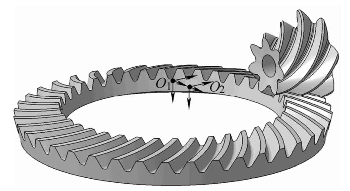
Figure 1 shows the geometric model of a pair of hypoid spiral bevel gears machined by the tool inclination method.
2. Finite element model of spiral bevel gear
Because the quadratic element will lead to the oscillation of the equivalent node contact force between the corner node and the node in the edge. Therefore, the eight node primary hexahedron isoparametric element is used to discretize the model. Due to the large helix angle of hypoid spiral bevel gear, mesh distortion will inevitably occur when dividing regular hexahedral elements. Therefore, when selecting the element integration form, the reduced integration element with little influence on the analysis accuracy due to the distortion of the grid can be selected. At the same time, the accuracy and speed of the reduced integration element are superior to the complete integration. Therefore, the linear reduced integral element is used here.
3. Application method of boundary conditions for finite element analysis of spiral bevel gears
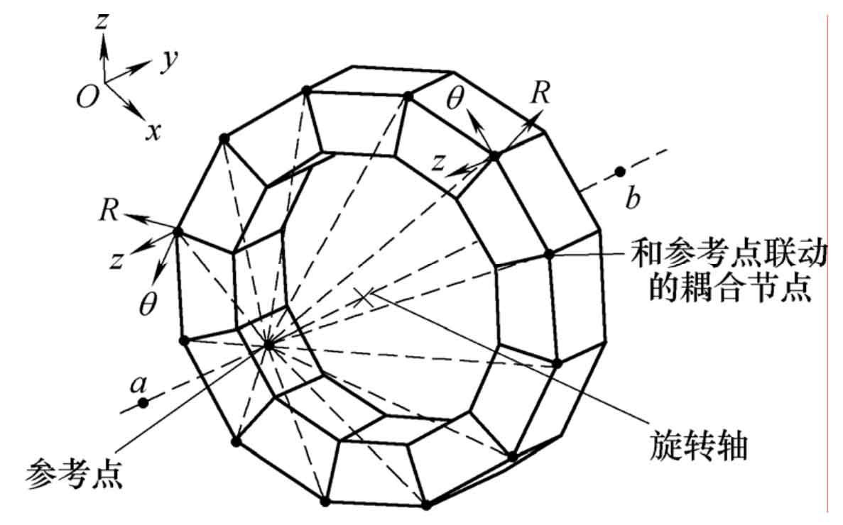
In the finite element software, the three-dimensional solid element generally does not have the degree of freedom of rotation, and the boundary conditions of spiral bevel gear are mainly applied to the degree of freedom of rotation. Therefore, the reference point can be established on the gear axis, and the coupling constraint can be established between the reference point and the inner ring and section of the large and small wheel, and the torque load and fixed constraint can be applied to the reference points of the small wheel and the large wheel. The coupling constraint process is shown in Figure 2. After the coupling constraint is established between the reference point and the coupling node, a rigid body connection is formed between the reference point and the coupling node, and the boundary conditions imposed on the reference point will be equivalent to the coupling node. The boundary conditions of pressure on the tooth surface due to the torque of the large wheel can be simulated by coupling constraints.