1. Calculation Model
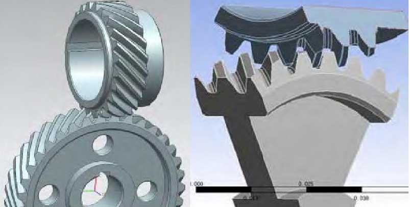
In order to investigate the contact stress on the tooth surface of this transmission staggered helical gear, the finite element calculation and analysis of the staggered helical gear is carried out by using Ansys software. The figure shows the assembly of the staggered helical gear and the finite element calculation model.In the figure, the upper part is the driving wheel and the lower part is the driven wheel. In the process of model simplification, a part of the teeth of the driving wheel and the driven wheel are analyzed in the finite element calculation respectively.

2. Grid division and calculation setup
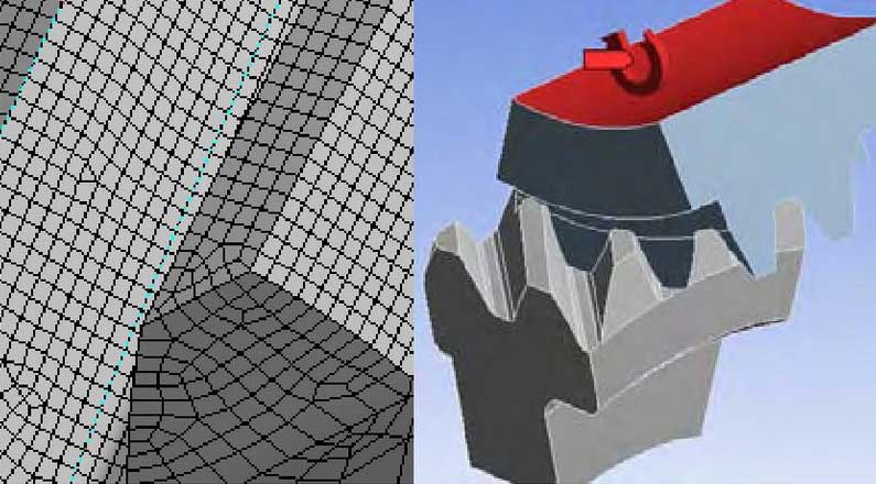
The mesh division is mainly based on hexahedral mesh and the contact tooth surface is encrypted.In calculation restraint setting, cylindrical restraint is applied to the driving wheel to keep free circumferential rotation and torque, and the calculated torque is 3.43N.m. according to power; fixed restraint is applied to the driven wheel.Graphs are grid partitions and constraint settings for models.According to the calculation of relevant parameters of the staggered helical gears of the unit, the coincidence degree is 1.83. Therefore, two pairs of teeth engage at the same time. Two pairs of contact pairs are set in the finite element calculation.

3. Calculation results and analysis
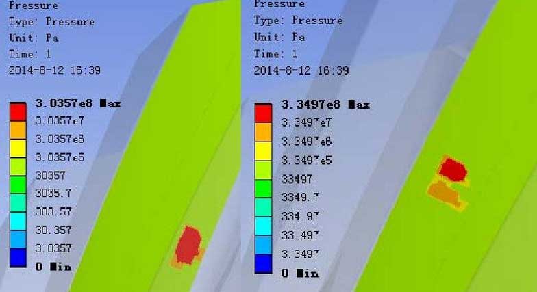
The figure shows the finite element calculation results. The contact occurs near the root and the top of the tooth respectively. It can be seen from the figure that the stress is mainly concentrated in a small area with a maximum stress of about 335 MPa.

Check the surface fatigue limit value Hlim of the helical gear material, the driven wheel is cast in sand mould, and the driving wheel is quenched and hardened without carburizing, Hlim=199MPa.According to the previous calculation results, the calculated contact stress is greater than the fatigue limit value and therefore prone to wear.
