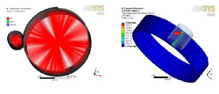
In the process of helical gear transmission, the tooth surface contact deformation is caused by sudden change load, and the inclined contact line becomes the contact area. The transient dynamic finite element analysis can be used to solve the dynamic problems of the transmission system under the action of load excitation. The time-domain distribution of elastic deformation or contact stress can be obtained, and the transient characteristics of helical gear transmission system can be obtained.
When the contact surface and the target surface are set, the dynamic friction coefficient is 0.06, the asymmetric contact behavior is set, and the normal contact stiffness coefficient is 1. The influence of damping should be considered in transient dynamic analysis. The constant small damping coefficient should be set as 0.1, so that the damping coefficient will not change with frequency, and the free vibration amplitude of the system will decay exponentially. The swept division method is used to divide the boundary line to simplify the mesh generation of the gear model, and the hexahedron structured mesh element is generated, and the rigid region is established on the inner surface. A gradual angular velocity of 3 120 (°) / S is applied to the driving wheel and a time-varying load torque is applied to the driven wheel. The size of time step will directly affect the accuracy of calculation, so it is necessary to consider the setting of time step. The calculation formula of initial time is as follows:

Where FI is the natural frequency value of the gearbox system when it is close to the rotational frequency.

The finite element model of helical gear is shown in the figure, and the maximum contact stress of tooth surface is shown in the figure.
