
High-speed railway transportation has become one of the most important transport modes in the world because of its high speed and large carrying capacity. The development of 100-meter heavy rails has been established as a key technical policy to ensure the stability and safety of high-speed trains. The lifting and handling of 100-meter heavy rails is a critical step in rail production. The smoothness and precision of the lifting process directly affect rail deformation, surface damage, and the safety of storage and stacking. Traditional hoisting methods use wire rope drums with multiple cranes and multiple lifting points. Although several rails can be lifted in groups, this approach has several disadvantages: poor Z-axis synchronization, uneven load distribution among lifting points, possible local rail dropping when electromagnetic chucks are used, large lateral swing caused by wire rope flexibility, rail torsion and uneven stress, and poor adaptability to wind-induced swing in outdoor environments.
To overcome these problems, I proposed a new lifting scheme based on rack and pinion gears. Compared with wire rope drum transmission, rack and pinion gears offer high transmission power, high efficiency, precise and controllable lifting distance, high stiffness, inherent anti-sway characteristics, long service life, and stable operation. The rack and pinion gears configuration can improve the synchronization and accuracy of heavy rail lifting, reduce deformation and surface damage, and increase the safety of storage and stacking. In my design, I used a single drive motor to actuate multiple meshing points through worm gear reducers. This single-drive multi-point meshing rack and pinion gears scheme reduces the number of motors, simplifies the mechanical structure, and improves synchronization.
However, during virtual assembly of the single-drive multi-point meshing rack and pinion gears, I found that the gear teeth could not mesh correctly. A clear tooth interference appeared. This interference problem prevents correct assembly and may cause tooth impact, tooth breakage, and abnormal vibration. Therefore, I focused my research on the interference of rack and pinion gears in a single-drive multi-point meshing configuration. I derived a method to calculate the interference amount, proposed a modification coefficient method to eliminate the interference, and verified the solution by finite element simulation and prototype testing.
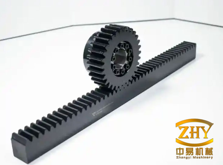
The rack and pinion gears are the core transmission elements in this research. The term rack and pinion gears appears throughout this article because the entire lifting mechanism depends on the meshing behavior of these components. I will present the design process, strength calculations, interference analysis, modification coefficient method, finite element simulation, and prototype validation.
Design and Load Capacity of Rack and Pinion Gears Transmission
I first established the basic design data for lifting 100-meter heavy rails. The lifting mechanism uses electromagnetic chucks, and each group contains seven rails. The total load per lifting point is 7.6 tons. Sixteen lifting points are arranged along the rail, with a spacing of 6 meters between adjacent points. The lifting system uses V-shaped guide rails for guidance, and rack and pinion gears are used for transmission. The lifting speed is low, and the gear rotational speed is 7.76 r/min, corresponding to a linear speed of 5 m/min. Because rack and pinion gears do not have self-locking capability, I selected a worm gear reducer to provide self-locking and a large reduction ratio. The lifting motor is a variable-frequency brake motor.
The initial design used a pair of gears symmetrically arranged with a single rack. The gear module was 10, the number of teeth was 10, and the pressure angle was 20 degrees. The material was 40Cr with surface quenching after tempering, and the hardness was 48 to 55 HRC. The rack material was 45 steel with a hardness of 240 HB. The gear precision grade was 7. The torque required for each gear was calculated as follows:
$$T_1 = \frac{G d}{2} = \frac{76000 \times 200}{2} = 3800000 \ \text{N}\cdot\text{mm}$$
I used the bending strength design formula for rack and pinion gears:
$$m_n \geq \sqrt[3]{\frac{12.4 K T_1 Y_{Fa}}{\phi_d z_1^2 \sigma_F}}$$
where \(K\) is the load factor, \(T_1\) is the torque, \(Y_{Fa}\) is the tooth form factor, \(\phi_d\) is the face width coefficient, \(z_1\) is the number of teeth, and \(\sigma_F\) is the allowable bending stress. The bending stress was calculated as:
$$\sigma_F = \frac{K F_t Y_{Fa} Y_{Sa} Y_\varepsilon}{b m_n} \leq [\sigma_F]$$
For the contact fatigue strength, I used the Hertz stress method. The contact stress for rack and pinion gears is given by:
$$\sigma_H = Z_H Z_E Z_\varepsilon \sqrt{\frac{2 K T_1}{d_1^3 \phi_d} \frac{u+1}{u}} \leq [\sigma_H]$$
where \(Z_H\) is the zone factor, \(Z_E\) is the elastic coefficient, \(Z_\varepsilon\) is the contact ratio factor, \(d_1\) is the pitch diameter, and \(u\) is the gear ratio. The allowable contact stress was determined from the material fatigue limit, safety factor, and life factor. The calculated contact stress for the one-pair scheme was 815.52 MPa, which is very close to the allowable stress of 843.75 MPa. Because this application is a heavy-duty lifting mechanism, the reliability margin was insufficient. Therefore, I abandoned the single-pair rack and pinion gears scheme.
I then designed a new scheme with two pairs of rack and pinion gears engaging a single rack. That is, four gears mesh with one rack, two on each side. The load per gear is halved, and the contact stress is significantly reduced. The contact stress for this four-gear scheme was calculated as:
$$\sigma_H = Z_H Z_E Z_\varepsilon \sqrt{\frac{2 K T_1}{d_1^3 \phi_d} \frac{u+1}{u}} = 576.66 \ \text{MPa} \leq 928.125 \ \text{MPa}$$
The bending strength and contact fatigue strength both satisfy the design requirements. Table 1 compares the two schemes.
| Scheme | Number of gears per rack | Contact stress (MPa) | Allowable stress (MPa) | Result |
|---|---|---|---|---|
| Scheme 1 | 2 | 815.52 | 843.75 | Insufficient reliability |
| Scheme 2 | 4 | 576.66 | 928.125 | Meets requirements |
To further reduce the number of drive motors and simplify the structure, I designed a single-drive multi-point meshing rack and pinion gears mechanism. One motor drives a worm gear, which drives two small intermediate gears. These small gears then drive four large gears that mesh with the rack. The four large gears are symmetrically arranged on both sides of the rack. This arrangement reduces the assembly size, lowers cost, and improves synchronization. The transmission capability was verified by calculating the normal load on each gear:
$$F_{ca} = K F_n = 1.67 \times \frac{2 T_1}{d_1 \cos \alpha} = 33766.361 \ \text{N}$$
The total load capacity of four gears is 135065.444 N, which is much larger than the required load of 76000 N per lifting group. Therefore, the single-drive multi-point meshing rack and pinion gears scheme is feasible.
Interference Analysis of Single-Drive Multi-Point Meshing Rack and Pinion Gears
After the single-drive multi-point meshing rack and pinion gears scheme was determined, I used standard involute spur gears and a standard rack for virtual assembly. During assembly, I found that the rack and pinion gears could not be assembled correctly, and tooth interference existed. I tested several other combinations of gear tooth numbers and rack parameters, and the interference phenomenon always appeared. Tooth interference occurs when the envelope of one gear enters the profile of another gear. If the pinion base circle and the gear addendum circle intersect along the pressure line and exceed the conjugate action limit, interference occurs. Interference can cause tooth impact, incorrect assembly, and tooth breakage. Therefore, it is necessary to solve the tooth interference problem.
To analyze the interference, I accumulated all interference at the last meshing position between gear 3 and the rack. I established a series of coordinate systems and derived the meshing relationship for gear 1 and gear 2, gear 2 and gear 3, and gear 3 and the rack. The gear parameters were: module \(m = 10\), pressure angle \(\alpha = 20^\circ\), number of teeth \(z_1 = z_3 = 25\), \(z_2 = 18\), addendum coefficient \(h_a^* = 1\), and clearance coefficient \(c^* = 0.25\).
The base circle equation for gear 1 is:
$$(x – a_1)^2 + (y – b_1)^2 = r_{b1}^2$$
where \(r_{b1} = \frac{m z_1 \cos \alpha}{2}\). The base circle equation for gear 2 is:
$$(x – a_2)^2 + (y – b_2)^2 = r_{b2}^2$$
where \(r_{b2} = \frac{m z_2 \cos \alpha}{2}\). The common internal tangent line of the two base circles is:
$$y = k_1 x + p_1$$
The distances from the centers of the two base circles to this tangent line are equal to the corresponding base circle radii:
$$\frac{|k_1 a_1 + p_1 – b_1|}{\sqrt{k_1^2 + 1}} = r_{b1}, \quad \frac{|k_1 a_2 + p_1 – b_2|}{\sqrt{k_1^2 + 1}} = r_{b2}$$
Solving these equations gives the slope and intercept of the common tangent. I then transformed the coordinate system so that the Y-axis passes through the intersection of the involute and the base circle. The involute equation of gear 1 is:
$$x_k = r_{b1} \sin u_k – r_{b1} u_k \cos u_k$$
$$y_k = r_{b1} \cos u_k + r_{b1} u_k \sin u_k$$
where \(u_k = \alpha_k + \theta_k\), \(\alpha_k\) is the pressure angle at point K, and \(\theta_k\) is the involute angle. The pressure angle at the addendum circle is:
$$\alpha_a = \arccos\left(\frac{r_b}{r_a}\right) = \arccos\left(\frac{z \cos \alpha}{z + 2 h_a^*}\right)$$
The involute function is:
$$\text{inv}\alpha = \tan \alpha – \alpha$$
The base tooth thickness is:
$$s_b = m z \cos \alpha \left(\frac{\pi}{2} + \text{inv}\alpha\right)$$
The central angle corresponding to the base tooth thickness is:
$$\tau = \frac{360^\circ s_b}{2 \pi r_b}$$
By counting the number of teeth between the meshing positions, I determined the rotation angles \(\delta_1\), \(\delta_2\), and \(\delta_3\) between the coordinate systems. The meshing point coordinates were obtained by solving the intersection of the common tangent line and the involute equation. This required an iterative method, and I used a program based on the golden section method or an fsolve function to find the solution.
For the meshing between gear 2 and gear 3, I repeated the same procedure. The common internal tangent of the base circles of gear 2 and gear 3 was found, and the involute equation of gear 2 was intersected with this tangent. After coordinate transformations, I obtained the meshing point Q in the coordinate system fixed to gear 3. Then, for the meshing between gear 3 and the rack, I established the rack pitch line and the rack tooth profile equation. The rack tooth profile is a straight line with an angle of 20 degrees to the rack pitch line. The interference amount \(\Delta\) was defined as the distance between two points M and N:
$$\Delta = \sqrt{(x_M – x_N)^2 + (y_M – y_N)^2}$$
where M is the intersection of the rack tooth profile and the line that passes through the meshing point and is tangent to the base circle of gear 3, and N is the meshing point of gear 3 and the rack. This distance represents the accumulated interference at the final meshing position.
For the numerical example, I used \(z_1 = z_3 = 25\), \(z_2 = 18\), \(m = 10\), and \(\alpha = 20^\circ\). The standard center distance between gear 1 and gear 2 is:
$$a = \frac{m(z_1 + z_2)}{2} = \frac{10 \times (25 + 18)}{2} = 215 \ \text{mm}$$
The base tooth thickness for gear 1 is:
$$s_{b1} = m z_1 \cos \alpha \left(\frac{\pi}{2} + \text{inv}\alpha\right) = 18.26199376 \ \text{mm}$$
The base tooth thickness for gear 2 is:
$$s_{b2} = m z_2 \cos \alpha \left(\frac{\pi}{2} + \text{inv}\alpha\right) = 17.28163085 \ \text{mm}$$
After solving the equations, I obtained the interference amount \(\Delta = 3.59 \ \text{mm}\). This means that the rack and pinion gears cannot mesh correctly without modification. The interference is caused by the accumulated tooth position errors from the multiple meshing points.
| Parameter | Gear 1 | Gear 2 | Gear 3 |
|---|---|---|---|
| Number of teeth | 25 | 18 | 25 |
| Module (mm) | 10 | 10 | 10 |
| Pressure angle (deg) | 20 | 20 | 20 |
| Base circle radius (mm) | 117.4615776 | 84.5723358 | 117.4615776 |
| Addendum circle pressure angle (deg) | 29.53139311 | 32.2504792 | 29.53139311 |
| Base tooth thickness (mm) | 18.26199376 | 17.28163085 | 18.26199376 |
Modification Coefficient Method for Solving Tooth Interference
The interference amount is directly related to the center distance between the gears and the rack. If the center distance can be slightly adjusted, the interference can be eliminated. Gear modification can adjust the center distance while maintaining correct meshing. Therefore, I proposed a modification coefficient method to solve the rack and pinion gears interference. The basic idea is to calculate the required change in center distance from the interference amount, then determine the total modification coefficient and distribute it between the meshing gears.
The standard center distance for a gear pair is:
$$a = \frac{m(z_1 + z_2)}{2}$$
To eliminate the interference, the actual center distance should be:
$$a’ = a – \frac{\Delta}{2}$$
For the numerical example, \(a = 215 \ \text{mm}\) and \(\Delta = 3.59 \ \text{mm}\), so:
$$a’ = 215 – \frac{3.59}{2} = 213.205 \approx 213 \ \text{mm}$$
The meshing angle \(\alpha’\) corresponding to the actual center distance is:
$$\alpha’ = \arccos\left(\frac{a}{a’} \cos \alpha\right) = \arccos\left(\frac{215}{213} \cos 20^\circ\right) = 19.25092324^\circ$$
For a pair of modified gears to mesh without backlash, the total modification coefficient \(x_\Sigma\) must satisfy the involute equation:
$$\text{inv}\alpha’ = \text{inv}\alpha + \frac{2 x_\Sigma \tan \alpha}{z_1 + z_2}$$
Thus, the total modification coefficient is:
$$x_\Sigma = \frac{(z_1 + z_2)(\text{inv}\alpha’ – \text{inv}\alpha)}{2 \tan \alpha}$$
Using the line diagram method for modification coefficient selection, I determined the total modification coefficient \(x_\Sigma = -0.1926\) for the gear pair with \(z_1 = 25\) and \(z_2 = 18\). The gear ratio is \(u = z_2 / z_1 = 18 / 25 = 0.72\). According to the distribution diagram, the modification coefficient for the small gear is \(x_1 = 0.03\), and for the large gear is \(x_2 = -0.2226\).
I also checked the undercut condition. The minimum modification coefficient to avoid undercut is:
$$x_{\min} = h_a^* – \frac{z \sin^2 \alpha}{2}$$
For the small gear with \(z_1 = 25\), \(x_{\min} = -0.0528\). For the large gear with \(z_2 = 18\), \(x_{\min} = -0.4622\). The selected modification coefficients \(x_1 = 0.03\) and \(x_2 = -0.2226\) are both greater than the minimum values, so no undercut occurs. Table 2 summarizes the modification coefficients.
| Gear | Number of teeth | Modification coefficient | Minimum coefficient for no undercut | Result |
|---|---|---|---|---|
| Small gear | 18 | 0.03 | -0.0528 | No undercut |
| Large gear | 25 | -0.2226 | -0.4622 | No undercut |
By applying these modification coefficients, the center distance is adjusted, and the accumulated interference at the rack and pinion gears is eliminated. The modified gears can mesh correctly without interference. This modification coefficient method provides a systematic way to solve the multi-point meshing interference problem.
Modeling and Finite Element Simulation of Modified Rack and Pinion Gears
To verify the modification coefficient method, I built three-dimensional models of the modified gears and rack. I used CAXA CAD to generate the involute tooth profile with the modification coefficients, and then I used SolidWorks to create the 3D models. The gear parameters are listed in Table 3.
| Parameter | Value |
|---|---|
| Module (mm) | 10 |
| Number of teeth (small gear) | 18 |
| Number of teeth (large gear) | 25 |
| Pressure angle (deg) | 20 |
| Face width (mm) | 40 |
| Modification coefficient (small gear) | 0.03 |
| Modification coefficient (large gear) | -0.2226 |
| Elastic modulus (GPa) | 211 |
| Poisson’s ratio | 0.3 |
| Density (kg/m^3) | 7820 |
Before modification, the virtual assembly showed clear interference. After modification, the assembly was successful, and the rack and pinion gears meshed correctly. I then exported the assembly to ABAQUS for explicit dynamic simulation. The material was 40Cr, and the rack material was 45 steel. The contact between gear teeth was defined as surface-to-surface contact. The mesh was refined at the meshing regions. The boundary conditions included a rotational speed of 0.314 rad/s on the driving gear and a torque of 4777500 N·mm on the driven gear.
The torque was calculated as:
$$T = \frac{G d}{2} = \frac{7800 \times 9.8 \times 10 \times 25}{2} = 4777500 \ \text{N}\cdot\text{mm}$$
The finite element simulation results showed that the maximum contact stress on the tooth surface was 802 MPa. The allowable contact stress for the material was 928.125 MPa. Therefore, the modified rack and pinion gears satisfy the strength requirement. The simulation also confirmed that the teeth mesh smoothly without interference. Table 4 presents the simulation results.
| Item | Value |
|---|---|
| Maximum contact stress (MPa) | 802 |
| Allowable contact stress (MPa) | 928.125 |
| Maximum bending stress (MPa) | Below allowable |
| Interference | Eliminated |
| Mesh quality | Good |
Based on the modified design, I manufactured a prototype of the single-drive multi-point meshing rack and pinion gears mechanism. The prototype was tested, and the results showed flexible operation, uniform tooth loading, low heat generation, and no interference. This further verified that the modification coefficient method is effective for solving the interference problem in single-drive multi-point meshing rack and pinion gears.
Conclusion
In this research, I proposed and designed a single-drive multi-point meshing rack and pinion gears transmission for lifting 100-meter heavy rails. The main conclusions are as follows:
First, rack and pinion gears can replace wire rope drum hoisting. The rack and pinion gears transmission provides precise lifting distance, high stiffness, and anti-sway characteristics, which improve the lifting quality of heavy rails.
Second, strength calculations showed that a two-gear single-rack scheme has insufficient load capacity, while a four-gear single-rack scheme meets the lifting requirements. The single-drive multi-point meshing rack and pinion gears mechanism uses one motor and a worm gear reducer to drive four large gears, reducing the number of motors and simplifying the structure.
Third, virtual assembly revealed tooth interference in the single-drive multi-point meshing rack and pinion gears. I derived a method to calculate the accumulated interference at the final meshing position. For the given parameters, the interference amount was 3.59 mm. I then proposed a modification coefficient method based on the relationship between center distance and interference. By selecting a total modification coefficient of -0.1926 and distributing it as 0.03 and -0.2226, the interference was eliminated.
Fourth, I built 3D models of the modified rack and pinion gears and performed finite element simulation. The maximum contact stress was 802 MPa, which is below the allowable stress of 928.125 MPa. The simulation confirmed that the modified rack and pinion gears mesh correctly without interference. A prototype was manufactured and tested, and the results verified the effectiveness of the modification coefficient method.
In summary, the modification coefficient method provides an effective solution to the interference problem of single-drive multi-point meshing rack and pinion gears. This method can be applied to heavy rail lifting and other similar heavy-duty transmission systems. Future work should consider lubrication for open rack and pinion gears, improve the calculation accuracy of interference, and optimize the modification coefficient selection to simultaneously satisfy center distance and maximum gear strength.