
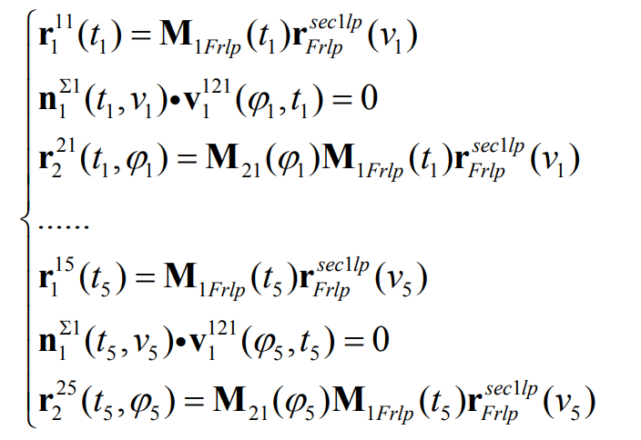
According to the method, the equiangular spiral bevel gear with five point contact can also be constructed. Because the section curve of the driving surface can be taken arbitrarily, the section curve of the pinion can also be similar to the design method of bevel gear, using double segment arc curve. Similarly, on the driving gear tooth surface Σ 1 after generation, five curves can be selected on the tooth surface, Γ 11… Γ 15, as contact wire. The spatial conjugate curves of the five spatial curves can be obtained by the method, Γ 21… Γ 25。 These 10 contact wires, Γ 11… Γ 25, expressed as:
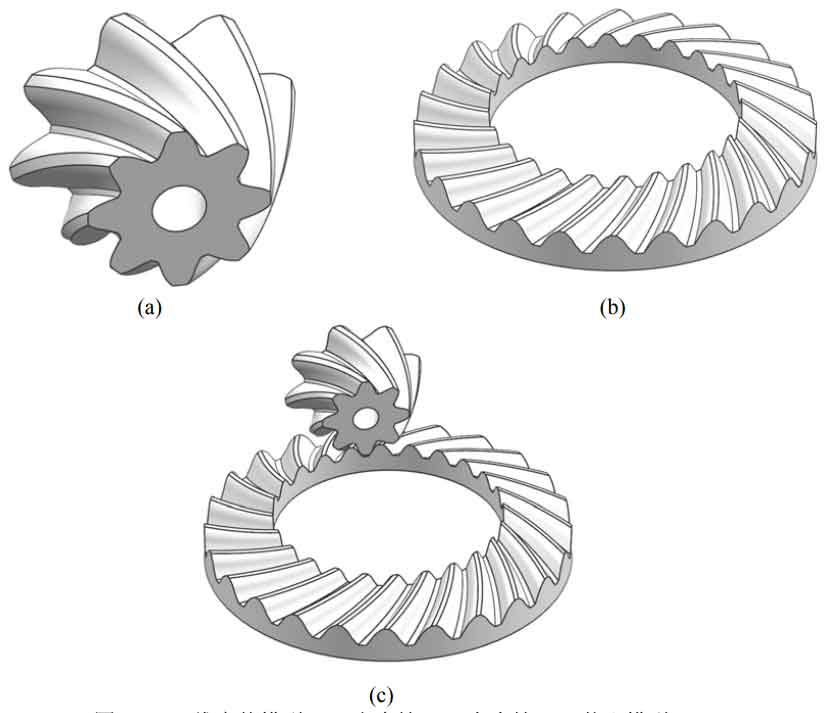
The tooth surface of the driven gear is adjusted by the method Σ 2 construct. Σ Section curve of 2 Γ S2 can still be designed as a multi segment regular curve, in the part between the contact lines, Γ S2 can be designed as a rational Bezier curve of order 3. In other parts, Γ S2 can be designed as an arc. Then, the tooth surface of bevel gear with five contact lines can be obtained. Here, set the same set of geometric parameters for modeling. Take R0 = 8mm, R1 = 15mm, R2 = 15mm, and construct a pair of bevel gears according to the above tooth surface method. The solid model is shown in Figure 1.
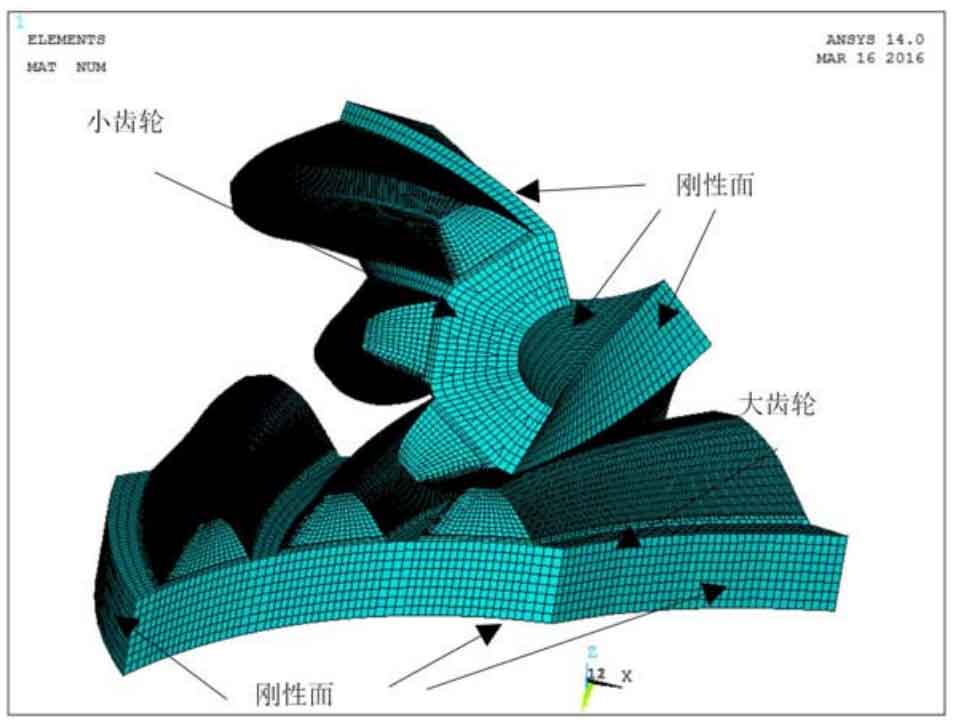
After the construction of bevel gear model, in order to evaluate its mechanical properties, the finite element analysis is carried out. The grid size setting, physical parameters, boundary conditions and their application methods are similar to those of double point contact equiangular spiral bevel gears. The final finite element model is shown in Figure 2. After solving the finite element model, the force distribution of pinion and big gear in power transmission is obtained.
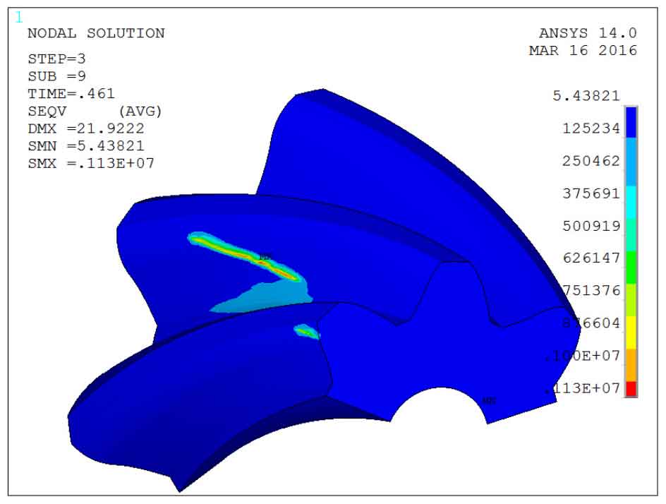
Figure 3 shows the bending and contact stress of the pinion when the contact point is located in the middle of the tooth surface of the bevel gear. Here, it can be seen that in the five point contact design, the contact area no longer presents a more obvious strip shape, and the strip contact area is connected by a plurality of elliptical contact areas.
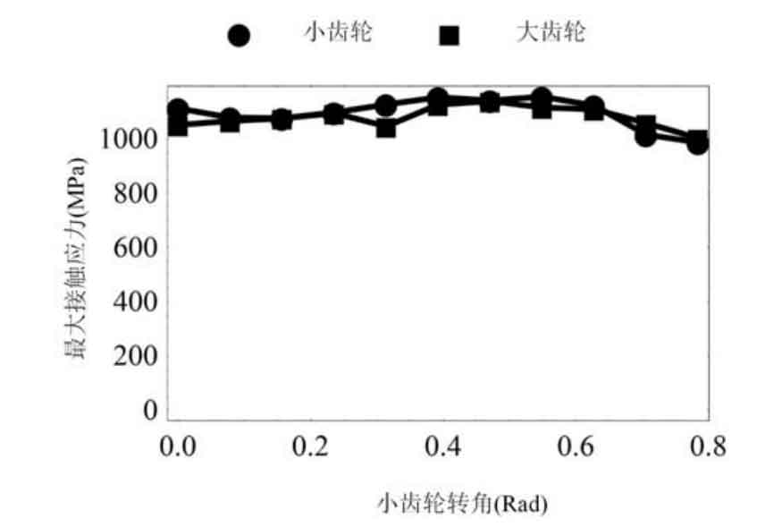
Fig. 4 shows the change of the maximum contact stress of a single tooth in a meshing cycle. It can be seen that the maximum contact stress is about 1100mpa. Compared with the double point contact equiangular spiral bevel gear, the contact stress of the five point contact equiangular spiral bevel gear is reduced by 10.1%. Therefore, it can be considered that the increase of instantaneous contact point can significantly reduce the contact stress, so as to improve the stress on the tooth surface.
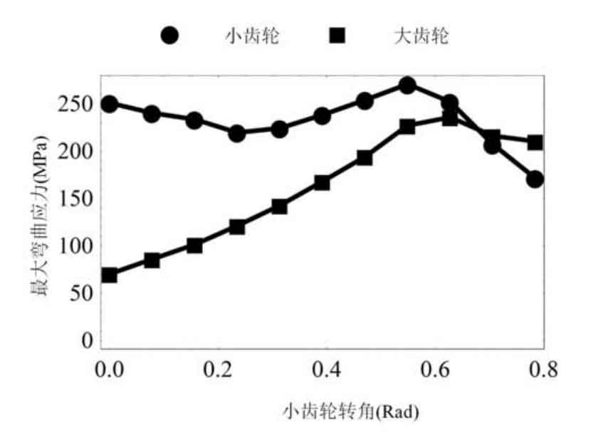
Fig. 5 shows the change of the maximum bending stress of a single tooth in a meshing cycle. It can be seen that the maximum bending contact stress has little difference from the maximum bending stress of single point and double point contact bevel gears, but the average value of the maximum bending stress decreases.