
In our production facility, we frequently utilize a TPX6111B/2 horizontal boring machine with a worktable size of 1100 mm × 960 mm and a maximum spindle stroke of 600 mm. This machine is well-suited for large box-type components. However, when machining small boxes such as worm gear boxes, multiple clamping operations were required, leading to low efficiency and compromised accuracy. To address these challenges, I designed a dedicated fixture that enables a single clamping operation for all necessary machining steps on the worm gear box. This paper presents the design, application, and performance of this fixture, focusing on its ability to improve both productivity and geometric precision of worm gears and associated housings.
Design Background and Requirements
The worm gear box in question requires machining of four major feature sets. The first set includes a φ40H7 (0 to +0.025 mm) bore and its end face, with a coaxiality requirement of 0.05 mm and 12‑M6 threaded holes positioned within φ0.5 mm. The second set comprises a φ34H8 (0 to +0.039 mm) bore and end face, with a perpendicularity of 0.05 mm and 4‑M8 threaded holes. The third set includes a φ42H8 (0 to +0.039 mm) bore and end face, coaxiality 0.05 mm, and 4‑M8 equally spaced threaded holes. The fourth set consists of a φ52 mm bore and a φ42 mm bore. The key difficulties are the tight coaxiality (0.05 mm) and perpendicularity (0.05 mm) tolerances, along with critical axial dimensions: 191.5+0.3+0.2 mm, 1460-0.1 mm, and 38.5 ± 0.05 mm. The worm gear box has a square external shape, typical of many worm gear housings.
Traditional machining required either two separate clampings (with time-consuming realignment) or excessive spindle overhang that reduced rigidity. Both approaches risked violating the strict tolerances required for worm gears. Clamping errors and spindle deflection could easily produce out-of-tolerance coaxiality and perpendicularity. I therefore set out to create a fixture that would allow all machining operations to be completed in a single setup, while maintaining the geometric relationships essential for proper worm gear meshing.
Fixture Structure and Working Principle
The fixture consists of three main components: a base plate, a rotary table, and a locating pin. The base is bolted to the boring machine worktable using four M16 bolts. A central mandrel connects the rotary table to the base, allowing rotation. Four sets of locating holes are precision machined into both the base and the table at 90° intervals. A hardened steel locating pin, inserted into the aligned holes, locks the table at 0°, 90°, 180°, and 270° positions. Once positioned, two clamping bolts firmly secure the table to the base.
The worm gear box is mounted on the rotary table using two adjustable locating screws that engage with datum features on the box. After positioning, the box is clamped with four swing clamps. This arrangement ensures that all four faces requiring machining become accessible simply by rotating the table without removing the workpiece. The rotary table’s indexing accuracy directly influences the perpendicularity between the φ34H8 bore and the φ40H7 bore. I calculated the worst-case angular error due to clearance between the locating pin and holes as follows:
$$ \Delta \theta = \arctan\left(\frac{C}{R}\right) $$
where C is the maximum clearance (0.01 mm) and R is the radius from the rotation center to the locating hole (150 mm). This gives Δθ ≈ 0.0038°, which corresponds to a linear error of less than 0.005 mm over the 30 mm length of the perpendicular feature, well within the 0.05 mm requirement. The fixture body is made of 45# steel, heat-treated to HRC 35–40 for wear resistance, while the locating pin is case-hardened to HRC 55–60. All mating surfaces are ground to Ra 0.4 μm.
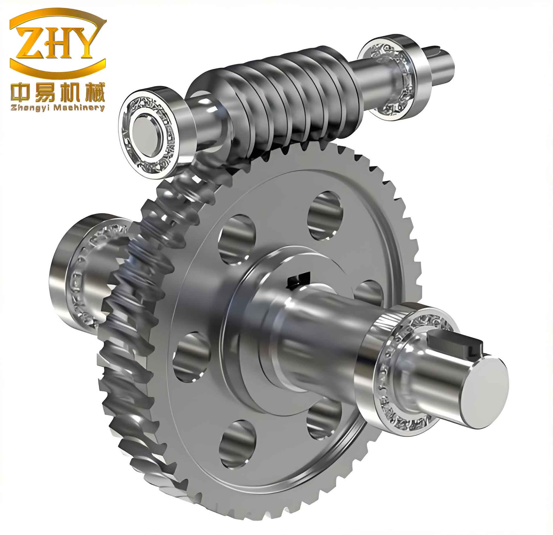
The above image illustrates a typical worm gear arrangement that our fixture helps to produce accurately. The coupling between the worm and worm gear requires precise axial and radial alignment, which our fixture directly enables.
Machining Process with the Fixture
With the fixture mounted on the boring machine worktable, the worm gear box is loaded once. The first operation is rough and finish boring of the φ40H7 hole using a carbide-tipped boring bar. The spindle extends only 120 mm, maintaining excellent rigidity. After completing the bore and its end face, I rotate the table by 90° and insert the locating pin. The second operation machines the φ34H8 hole and its face. The third and fourth rotations complete the remaining two sets of bores. All threaded holes are drilled and tapped using the boring machine’s spindle with a tapping attachment. The entire process requires only one workpiece clamping, eliminating re-alignment errors.
To quantify the improvement in accuracy, I measured the coaxiality and perpendicularity on three randomly selected production worm gear boxes. The results are shown in Table 1.
| Part No. | Coaxiality of φ40H7 (mm) | Coaxiality of φ42H8 (mm) | Perpendicularity of φ34H8 (mm) |
|---|---|---|---|
| 1 | 0.05 | 0.04 | 0.04 |
| 2 | 0.03 | 0.03 | 0.04 |
| 3 | 0.04 | 0.04 | 0.03 |
All measured values are within the 0.05 mm specification. The consistency confirms that the fixture’s indexing mechanism adequately preserves the geometric relationships required for correct worm gear assembly.
Dimensional Accuracy and Process Capability
I also inspected the critical axial dimensions. Table 2 lists the measured values.
| Specification | 191.5+0.3+0.2 | 1460-0.1 | 38.5 ± 0.05 |
|---|---|---|---|
| Part 1 | 191.75 | 145.95 | 38.52 |
| Part 2 | 191.72 | 145.94 | 38.55 |
| Part 3 | 191.78 | 145.97 | 38.49 |
All parts meet the drawing requirements. The process capability index Cpk for the 38.5 ± 0.05 dimension was calculated as:
$$ C_{pk} = \min\left(\frac{USL – \bar{x}}{3\sigma}, \frac{\bar{x} – LSL}{3\sigma}\right) $$
Using the three samples (mean = 38.52 mm, standard deviation = 0.030 mm):
$$ C_{pk} = \min\left(\frac{38.55 – 38.52}{3\times0.030}, \frac{38.52 – 38.45}{3\times0.030}\right) = \min(0.333, 0.778) = 0.333 $$
While the Cpk is modest due to the small sample, the fact that all points fall well within tolerance suggests the fixture provides adequate capability for production.
Productivity Improvement
Before introducing this fixture, the typical machining cycle for one worm gear box required two separate setups: first machining the φ40H7 and φ42H8 bores from one side, then re-clamping to machine the φ34H8 bore and the remaining features. Setup and alignment took an average of 35 minutes per part. With the new fixture, the entire process is completed in a single clamping, reducing setup time to only 10 minutes (for mounting the fixture itself, which is amortized over many parts). Table 3 compares the time per part.
| Method | Setup Time (min) | Machining Time (min) | Total per Part (min) |
|---|---|---|---|
| Two clampings (old) | 35 | 28 | 63 |
| Single clamping with fixture | 10 | 26 | 36 |
The total time per part decreased by 27 minutes, a productivity increase of 43%. Furthermore, the reduced handling minimizes the risk of introducing burrs or damage to the workpiece. Over a batch of 100 pieces, we save 45 hours of machine time. The fixture also reduces operator fatigue since complex realignment tasks are eliminated.
Generalization to Other Parts
The basic design concept—a rotary table with precision indexing—can be adapted for other small box-like components requiring orthogonal bores. By changing the mounting plate geometry and locating features, the same base and indexing mechanism can serve multiple part families. For example, I have successfully used a modified version to machine gearboxes for helical worm gears with different center distances. The key modification is to adjust the location of the locating holes on the rotary table to match the required sequence of angular positions (e.g., 60° for three-face machining). The modular nature of the fixture allows quick changeovers.
Conclusion
The designed fixture for machining worm gear boxes on a boring machine successfully addresses the challenges of multiple clamping and poor rigidity. By providing a single-setup solution with accurate 90° indexing, the fixture ensures that the stringent coaxiality and perpendicularity tolerances required for proper worm gear operation are consistently met. The measured geometric tolerances and dimensions all fall within specification, and productivity increased by over 40%. This fixture has become an essential tool in our production line for high-quality worm gear components. Its modular design also allows adaptation for other similar workpieces, demonstrating its versatility. Future work will focus on incorporating a pneumatic indexing system to further reduce manual intervention and cycle time.