
Due to the generality of the finite element method, the force analysis of pure rolling contact isometric helix conjugate curve bevel gear can still be carried out by the finite element method. For the solid of equidistant spiral bevel gear, the low-order hexahedron element solid185 element is selected to divide the large and small parts of the grid. Near the contact area, the unit side length of the part participating in the contact tooth surface is set to 0.2mm, and the unit side length of other parts is set to 1-2mm. The final mesh model is shown in Figure 1. Among them, the binding contact pair based on multi-point constraint algorithm is established between the bottom surface of the big gear and the rotation center point, and the binding contact pair based on multi-point constraint algorithm is also established between the inner wall of the pinion and the rotation center point. Then 184 elements with their respective rotation axes as degrees of freedom kinematic constraints are established for the large and small gears between the rotation center node and the absolute coordinate system. The physical parameter Young’s modulus is 2.05 × 10⁵Mpa, Poisson’s ratio is 0.3. For the boundary load, set the output load to 540nm. Finally, apply 180nm input torque on the pinion and 0.3rad/s speed on the big gear.

After solving the finite element model, the force distribution of pinion and big gear in power transmission can be obtained. Figure 2 shows the bending and contact stress of the pinion when the contact point is located in the middle of the tooth surface. According to Hertz contact theory, when the two contact surfaces of point contact are in actual contact, the shape of the contact area is ellipse due to the action of elastic deformation. Because the bending deformation of tooth root will affect the actual contact condition of equidistant spiral bevel gear, the contact area is only approximate ellipse in the finite element analysis results.
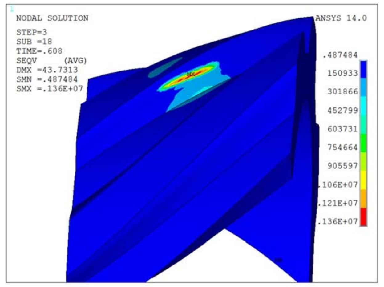
Fig. 3 shows the change of maximum contact stress of single tooth of isometric spiral bevel gear in one meshing cycle. It can be seen that the maximum contact stress is 1400MPa, which appears in the middle of the tooth surface. This is because when the contact point is located in the middle of the tooth surface, only a single tooth carries the load and the load is not shared, so it has a large contact stress. Figure 4 shows the change of the maximum bending stress of a single tooth of the equidistant spiral bevel gear in a meshing cycle. The maximum bending stress is 350Mpa, which appears on both sides of the tooth surface. This is due to the sudden change of the tooth geometry on both sides of the equidistant spiral bevel gear tooth surface, resulting in stress concentration.

