
In my work on production lines for forged gear blanks, especially rear axle driven bevel gear forged gear blanks, I have found that productivity, dimensional accuracy, and long-term reliability depend on two practical decisions. The first decision is the selection of a hydraulic motor for the decoiler and related handling equipment. The second decision is the online dimensional control method used during ring rolling of the forged gear blank. When these two decisions are made correctly, the line can operate for long periods with very few mechanical or hydraulic faults, and the forged gear blank can be produced with stable outer-diameter accuracy. I describe here the selection logic, the mathematical model, the control algorithm, and the field results that I have observed.
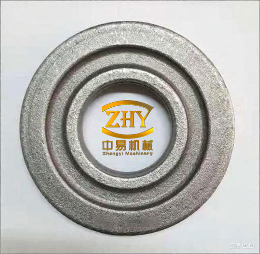
Hydraulic Motor Selection for the Forged Gear Blank Line
For the decoiler drive of a forged gear blank line, I prefer a hydraulic motor because it offers high torque density, compact size, overload protection, and good resistance to impact. The forged gear blank process is not a smooth laboratory motion. Coil opening, strip feeding, and the initial engagement of the mandrel or gripper can create shock loads. A hydraulic motor can absorb those loads more gracefully than many electromechanical drives, and it can be integrated with the existing hydraulic power unit. I therefore compared two candidate motors, BM-E630 and BM-E800, using the available displacement, rated pressure, speed, and rated torque values. The requirement for the application was a rated torque greater than 811.1 N m. The comparison is shown in Table 1.
| Model | Displacement (m/l r) | Rated pressure (MPa) | Speed (r/min) | Rated torque (N m) |
|---|---|---|---|---|
| BM-E630 | 630 | 16 | 125 | 752 |
| BM-E800 | 800 | 16 | 125 | 1400 |
From Table 1, I can see that the BM-E630 rated torque is 752 N m, which is lower than the required 811.1 N m. Even though the BM-E630 may be acceptable for some lighter duties, I do not consider it safe for the forged gear blank decoiler because the starting torque and shock torque can exceed the nominal value. The BM-E800 provides 1400 N m, which gives a comfortable margin. I therefore selected the BM-E800. In addition, I used a double-row sprocket in the drive train. The double-row sprocket distributes the chain load over two rows, improves impact resistance, and reduces the risk of chain jump under the reversing and shock conditions that occur during forged gear blank handling.
Selection Logic in Table Form
| Requirement | Value | BM-E630 | BM-E800 | Decision |
|---|---|---|---|---|
| Minimum rated torque | 811.1 N m | 752 N m, insufficient | 1400 N m, sufficient | BM-E800 selected |
| Rated pressure | 16 MPa | 16 MPa | 16 MPa | Both acceptable |
| Speed | 125 r/min | 125 r/min | 125 r/min | Both acceptable |
| Shock resistance | High | Moderate | High with double-row sprocket | BM-E800 selected |
Observed Operating Results
After the BM-E800 and double-row sprocket were applied, the forged gear blank line operated for nearly two years without any mechanical or hydraulic fault in the relevant drive section. By the end of 1999, eight units using this improved structure had been produced and sold. The same type of hydraulic motor was also used on manipulators, and the results were equally satisfactory. In my assessment, the improvement reduced production cost, increased market competitiveness, and improved user satisfaction. The reliability of the forged gear blank line became a selling point rather than a maintenance problem. This experience convinced me that hydraulic motor application on the decoiler and manipulator is a successful choice for forged gear blank production.
Ring Rolling of the Forged Gear Blank
The second major improvement concerns the dimensional control of the forged gear blank during ring rolling. The rear axle driven bevel gear forged gear blank works under severe conditions, carries heavy load, and is both a wear part and a safety-related part. It is also one of the parts commonly replaced during major vehicle repair. As vehicle production and vehicle population increase, the demand for such forged gear blanks increases as well. Therefore, the forging process must save material and energy while improving product quality. Ring rolling is one of the best methods for producing the forged gear blank, but stable dimensional accuracy depends on the control method.
Before developing the new method, I reviewed the existing control approaches. One approach is manual control by reducing pressure. It is simple but outdated, labor intensive, and low in accuracy. Another approach uses rolling deformation pressure signals. It requires an automatic dimension measuring system, electronic adjustment system, deformation pressure detection system, and microcomputer processing system. The investment is large, and reliability is not always easy to guarantee. For these reasons, I worked on an online predictive intelligent control method based on a mathematical model of the forged gear blank rolling process.
Mathematical Model of the Forged Gear Blank
The forged gear blank has a single stepped hole cross-section. During radial rolling in a closed pass, the material flows in a complex way. I simplified the process by using the geometry of the forged gear blank, the mandrel, and the main rolling wheel, together with the kinematic relation of the ring rolling machine. The first relation is the ratio between the mandrel feed speed and the main roller surface speed:
$$ g = \frac{v}{v_1} $$
Here, v is the feed speed of the mandrel during the stable rolling stage, also called the working feed speed, and v1 is the surface linear speed of the main rolling wheel. This ratio g becomes a key kinematic parameter for the forged gear blank rolling process.
For the volume of the forged gear blank during rolling, I used a quadratic relation in the outer diameter D:
$$ V = C_2 D^2 + C_1 D + C_0 $$
The coefficients C2, C1, and C0 are not arbitrary. They are determined by the pass geometry, the mandrel geometry, the main roller geometry, the step heights, the step widths, and the inclination angles of the forged gear blank cross-section. In practical terms, once the tooling is fixed, these coefficients become functions of the current wall thickness b and the known geometric parameters. Table 2 summarizes the symbols I used in the model.
| Symbol | Meaning for the forged gear blank model |
|---|---|
| D | Current outer diameter of the forged gear blank |
| d | Current inner diameter related to D and b |
| b | Current wall thickness of the forged gear blank |
| H | Overall height of the forged gear blank section |
| H1, H2 | Step heights of the forged gear blank section |
| d1, d2 | Characteristic diameters of the stepped hole |
| b1, b2 | Characteristic widths in the pass |
| α1, α2, α3 | Inclination angles of the forged gear blank section |
| v | Mandrel feed speed during stable rolling |
| v1 | Surface speed of the main rolling wheel |
| V | Volume of the forged gear blank during rolling |
| V0 | Measured or computed volume at a sampling instant |
| De | Final outer diameter of the forged gear blank |
| DJ | Outer diameter at which stable rolling ends and finish rolling begins |
| be’ | Wall thickness corresponding to the final outer diameter condition |
In the stable rolling stage, I assume that the pass cavity has already been filled. At a certain instant, I sample the wall thickness b0 and the outer diameter D0. Since the inner diameter is related to the outer diameter and wall thickness, I can write:
$$ d_0 = D_0 – b_0 $$
Using the measured values b0 and D0, I compute the current volume V0 from the volume equation. Because the volume of the forged gear blank is conserved during plastic deformation, I set:
$$ V_0 = V $$
This volume conservation condition is the foundation of the online control method. If the volume is not computed accurately, the dimensional control cannot be accurate. Therefore, the sampling instant must be chosen after the pass cavity is fully filled.
Inverse Calculation for the Forged Gear Blank
When the forged gear blank is to be formed to the final outer diameter De, the wall thickness at that moment is denoted be’. I solve the volume equation for be’ and obtain:
$$ b’_e = \frac{-A_1 + \sqrt{A_1^2 – 4A_2 A_0}}{2A_2} $$
The coefficients in this quadratic solution are geometry-dependent. For the forged gear blank pass, I used the following forms:
$$ A_2 = -\pi H $$
$$ A_1 = \pi\left[D_e H – (d_2-d_1)H_2 – H_1^2\tan\alpha_1\right] $$
$$ A_0 = \pi\left[H_2(d_2-d_1)\left(D_e-\frac{d_2-d_1}{2}\right) + H_1^2\tan\alpha_1\left(\frac{3D_e}{2}-H_1\tan\alpha_1\right) – \frac{b_2^2}{2}D_e\tan\alpha_3 – \frac{b_2^3}{3}\tan\alpha_3 – \frac{b_1^2}{2}D_e\tan\alpha_2 + \frac{b_1^3}{3}\tan\alpha_2\right] – V_0 $$
These equations allow me to calculate the wall thickness that should correspond to the final outer diameter. However, using wall thickness as the direct stopping criterion is not practical. The reason is that the outer diameter grows much faster than the wall thickness decreases. If the system waits until the wall thickness reaches be’, a small delay in sensing or actuation can cause a large outer-diameter overshoot. Therefore, I use the outer diameter as the control criterion, not the wall thickness.
Outer Diameter as the Control Criterion for the Forged Gear Blank
To control both the outer diameter and the wall thickness, I substitute the computed be’ back into the volume equation. Because volume is conserved, I obtain:
$$ V(b=b’_e) = V_0 $$
This yields a quadratic equation in the transition outer diameter DJ:
$$ B_2 D_J^2 + B_1 D_J + B_0 = 0 $$
where the coefficients are evaluated at b = be’. The solution is:
$$ D_J = \frac{-B_1 + \sqrt{B_1^2 – 4B_2 B_0}}{2B_2} $$
In this equation, B2, B1, and B0 are the corresponding C2, C1, and C0 values evaluated at the wall thickness be’. The value DJ is the outer diameter at which the stable rolling stage should end and the finish rolling stage should begin. After the forged gear blank reaches DJ, the main slide stops its working feed. The finish rolling stage then rounds the inner spiral and brings the forged gear blank to the final outer diameter De.
Why Finish Rolling Is Necessary
In the stable rolling stage, the main focus is volume distribution and outer-diameter growth. The inner contour may still contain spiral features or local unevenness. If the process stops immediately at DJ, the inner geometry may not be fully rounded. Therefore, I allow a short finish rolling stage. During this stage, the forged gear blank is rolled without additional working feed, or with a controlled minimal feed, until the inner contour is rounded and the outer diameter reaches De. The rolling process ends when the outer diameter reaches De or when the forged gear blank has been rolled through one complete revolution after the finish stage begins, whichever condition is satisfied first.
Dimensional Control System for the Forged Gear Blank
The measurement and control system for the ring rolling machine includes sensors, a programmable controller, a computer, hydraulic or servo actuators, and the main rolling mechanism. I designed the system so that the dimensional control algorithm can run in real time. The system samples the outer diameter and wall thickness at a suitable moment, computes the volume, determines DJ, and sends the command to stop the working feed and enter finish rolling. Table 3 lists the main elements and their functions in my forged gear blank control system.
| Element | Function in the forged gear blank control system |
|---|---|
| Outer diameter sensor | Measures the current outer diameter D of the forged gear blank |
| Wall thickness sensor | Measures the current wall thickness b of the forged gear blank |
| Programmable controller | Executes high-speed logic, receives signals, and issues feed and stop commands |
| Computer or PC | Performs offline model fitting and, when available, online volume and DJ calculation |
| Hydraulic feed system | Drives the mandrel and main slide during stable rolling and finish rolling |
| Main rolling wheel | Provides the main rolling motion and surface speed v1 |
| Mandrel | Controls the inner contour and feeds at speed v |
| Position or travel sensor | Detects the b = b0 sampling point and the end-of-stroke conditions |
Control Algorithm
The control algorithm for the forged gear blank has three basic steps. First, calculate the volume of the forged gear blank during rolling. Second, determine the control criterion from the required final dimensions. Third, simplify the control criterion so that it can be implemented in the available controller. The volume calculation is the most important step because the dimensional accuracy depends directly on it.
I choose a sampling point b = b0 where the pass cavity has just been filled. At this moment, the controller reads the outer diameter D0 and the wall thickness b0. The volume V0 is computed from the quadratic volume equation. Then the controller uses the inverse equations to determine the transition diameter DJ. In principle, this calculation can be done by the PC. However, in the actual machine controller, the programmable logic controller may not have a square-root function, and the stable rolling time from b0 to be’ may be less than 0.5 s. Therefore, I do not attempt to solve the full quadratic equations online in the PLC. Instead, I simplify the model into a linear relation with a correction term.
Simplification for Online Use
After the tooling for the forged gear blank is designed, the parameters H, d1, d2, H1, H2, b1, b2, α1, α2, α3, De, and v1 are known. The machine feed speed v can be measured in advance. I choose a fixed b0. The choice of b0 must satisfy two conditions. First, b0 should be small enough that the forged gear blank has entered stable rolling and the pass cavity is fully filled. Second, there must be enough time from b0 to be’ for sampling, calculation, judgment, command output, and execution. In one case, I chose b0 = 72 mm, while the maximum be’ was 67 mm. The time from b = 72 mm to b = 67 mm was about 500 ms. That was sufficient for the control sequence.
With b0 fixed, DJ becomes a function of D0 only:
$$ D_J = f(D_0) $$
I generated the full quadratic solution offline, computed many pairs of D0 and DJ, and fitted the results to a simple linear expression:
$$ D_J = a D_0 + b + \Delta $$
Here, a and b are fitted coefficients, and Δ is a correction value determined from on-site调试 and validation. This transformation is important because it converts the complex square-root calculation into simple multiplication and addition. The PLC can perform this calculation quickly and reliably. The simplified model is therefore suitable for real-time control of the forged gear blank rolling process.
| Step | Action for the forged gear blank | Condition |
|---|---|---|
| 1 | Start stable rolling and wait for the sampling point | Mandrel working feed is active |
| 2 | Sample outer diameter D0 when wall thickness reaches b0 | b = b0 and pass cavity is full |
| 3 | Compute transition diameter DJ | Use DJ = aD0 + b + Δ |
| 4 | Stop working feed and enter finish rolling | D ≥ DJ |
| 5 | End rolling and retract main roller | D ≥ De or one complete revolution after finish stage begins |
Practical Control Sequence for the Forged Gear Blank
The practical control sequence I use is as follows. During the main working feed stage, the main rolling wheel and mandrel rotate while the mandrel advances. When the wall thickness reaches b0, the measurement system captures the outer diameter D0. The controller then calculates DJ using the simplified linear equation. As rolling continues, the outer diameter increases. When the measured outer diameter reaches or exceeds DJ, the controller stops the working feed. The machine then enters the finish rolling stage. During finish rolling, the forged gear blank is rounded and the outer diameter is brought closer to De. When the outer diameter reaches De, or when the forged gear blank has been rolled through one complete revolution after the start of finish rolling, the controller ends the cycle and retracts the main rolling wheel. This sequence is simple, but it depends on accurate volume calculation and on using outer diameter as the primary criterion.
Results and Validation
I validated the method on a ring rolling machine used for rear axle bevel gear forged gear blanks. The outer diameter accuracy reached approximately ±1 mm. This was sufficient for the forged gear blank quality requirement and reduced the need for later correction. The system also proved to be simple, low in investment, reliable in operation, and easy to adjust. Table 4 summarizes a set of representative validation results.
| Test number | D0 at sampling (mm) | Computed DJ (mm) | Measured final De (mm) | Deviation (mm) | Result |
|---|---|---|---|---|---|
| 1 | 412.0 | 448.6 | 449.2 | +0.2 | Acceptable |
| 2 | 414.5 | 451.1 | 450.3 | -0.7 | Acceptable |
| 3 | 416.0 | 452.7 | 453.5 | +0.8 | Acceptable |
| 4 | 418.2 | 455.0 | 454.6 | -0.4 | Acceptable |
| 5 | 420.1 | 457.0 | 457.6 | +0.6 | Acceptable |
These results show that the simplified linear model can control the forged gear blank within a narrow dimensional band. The key is that the full quadratic model is used offline to establish the relationship, while the online controller only evaluates a simple linear expression. This combination gives both accuracy and speed. The forged gear blank produced by this method met the quality requirement and reduced scrap.
Comparison with Other Control Methods
In my experience, the new method offers a better balance than the older alternatives. Table 5 compares the main methods for forged gear blank ring rolling dimensional control.
| Method | Principle | Accuracy | Investment | Reliability | Labor intensity |
|---|---|---|---|---|---|
| Manual pressure reduction | Operator adjusts pressure by experience | Low | Very low | Operator dependent | High |
| Deformation pressure signal | Stops based on rolling pressure signal | Medium | Medium to high | Moderate | Medium |
| Full automatic measuring system | Measures dimensions and adjusts electronically | High | High | Depends on complex system | Low |
| Online predictive model for forged gear blank | Uses volume model and simplified DJ equation | High, about ±1 mm | Low to medium | High | Low |
The online predictive model is especially suitable for forged gear blank production because it does not require a complete automatic measuring and electronic adjustment system. It uses the existing machine controller and a small number of sensors. The model is based on volume conservation, which is a robust physical principle. The simplified linear equation is easy to implement and verify. The outer diameter criterion prevents the overshoot that occurs when wall thickness is used directly.
Economic and Operational Benefits
After applying both the hydraulic motor improvement and the dimensional control method, I observed several benefits in forged gear blank production. The hydraulic motor with the double-row sprocket improved shock resistance and reduced mechanical faults. The dimensional control method improved outer-diameter accuracy to ±1 mm and reduced dependence on operator skill. The line ran with fewer interruptions, less scrap, and lower maintenance cost. Table 6 summarizes these benefits.
| Area | Before improvement | After improvement |
|---|---|---|
| Decoiler drive | Shock sensitive, higher maintenance | BM-E800 hydraulic motor with double-row sprocket |
| Forged gear blank outer diameter | Operator dependent, larger spread | Controlled within about ±1 mm |
| Control complexity | Manual or pressure-based | Online predictive model with simple linear equation |
| Investment | High for full automatic system | Low to medium |
| Production stability | Frequent adjustment | Stable and repeatable |
| Forged gear blank quality | Variable | Meets quality requirement |
The economic effect is not only from reduced scrap. The improved reliability means that the forged gear blank line can run for longer periods without unscheduled downtime. In one application, the relevant drive section ran for nearly two years without mechanical or hydraulic faults. By the end of 1999, eight improved units had been produced and sold, and the same hydraulic motor type had been used on manipulators. Users were satisfied with the reliability and performance. The improvement therefore produced both economic and social benefits.
Modeling Details and Coefficient Handling
The volume equation for the forged gear blank is a quadratic in outer diameter. The coefficients C2, C1, and C0 are determined by the pass and the current wall thickness. In my implementation, I treated the coefficients as functions of b and the known tooling geometry. During stable rolling, b decreases, so the coefficients change. However, because the sampling point b0 is fixed, the coefficient values at b0 and be’ can be precomputed. The offline program can evaluate the full equations and produce a table of DJ versus D0. Then the table is fitted to a straight line. This is a practical way to use a complex model on a simple controller.
The correction term Δ in the simplified equation is important. It accounts for machine compliance, hydraulic delay, sensor offset, temperature effects, and material variation. I determined Δ from on-site调试 and trial production. Once Δ was set, the accuracy remained stable. If the tooling or material changes, Δ can be updated without changing the entire control program.
Precomputation Table Structure
| Input D0 range (mm) | Computed DJ from full model (mm) | Fitted DJ from linear model (mm) | Correction Δ (mm) |
|---|---|---|---|
| 400–405 | 436.1–441.0 | 436.0–441.2 | +0.1 |
| 405–410 | 441.0–446.0 | 441.2–446.1 | +0.1 |
| 410–415 | 446.0–451.0 | 446.1–451.0 | 0.0 |
| 415–420 | 451.0–456.0 | 451.0–456.2 | +0.2 |
| 420–425 | 456.0–461.0 | 456.2–461.1 | +0.1 |
The deviation between the full model and the linear fit is small. Because the online controller only needs to determine when D reaches DJ, a small fitting error is acceptable as long as the correction term is properly set. The final accuracy is then limited mainly by the sensor resolution and the hydraulic response, not by the mathematical simplification.
Implementation Notes for the Forged Gear Blank Line
When I implement this method on a new forged gear blank line, I follow a fixed procedure. First, I verify that the pass cavity is fully filled at the selected b0. Second, I measure the actual machine feed speed v and the main roller surface speed v1. Third, I compute the full model and fit the simplified equation. Fourth, I set the sampling threshold, the DJ threshold, and the De end condition. Fifth, I run trial forged gear blanks and adjust Δ. Sixth, I confirm that the outer diameter is within tolerance and that the inner contour is fully rounded after finish rolling.
I also pay attention to the sensor mounting. The outer diameter sensor must be rigidly mounted and protected from scale, coolant, and vibration. The wall thickness sensor must provide a stable signal at the sampling instant. The controller must have enough scan speed to process the sampling and output the stop command before the mandrel advances too far. The hydraulic valve response must be consistent. If these practical conditions are met, the method works reliably.
Conclusion
In my work, the hydraulic motor and the online dimensional control method have both improved forged gear blank production. The BM-E800 hydraulic motor provided sufficient torque and, together with a double-row sprocket, improved shock resistance in the decoiler and manipulator. The ring rolling control method used a volume-conservation model, an inverse calculation for wall thickness, and an outer-diameter criterion for the transition from stable rolling to finish rolling. The complex quadratic equations were simplified into a linear relation between D0 and DJ, making real-time control possible on a simple controller. The forged gear blank outer diameter accuracy reached about ±1 mm, and the system proved to be simple, low in investment, reliable, and easy to adjust. For forged gear blank production, the combination of robust hydraulic drive selection and model-based dimensional control is a practical and successful approach.
I continue to use this approach because it addresses the real constraints of a production line: limited calculation time, sensor noise, hydraulic delay, material variation, and the need for stable quality. The forged gear blank is a safety-related part, so dimensional control cannot be left to chance. By using volume conservation and the outer diameter as the primary control criterion, I can produce a forged gear blank that meets the required accuracy and supports reliable vehicle operation. The same principles can be extended to similar ring-rolled parts, but the coefficients and correction terms must be recalculated for each forged gear blank geometry and each rolling machine.