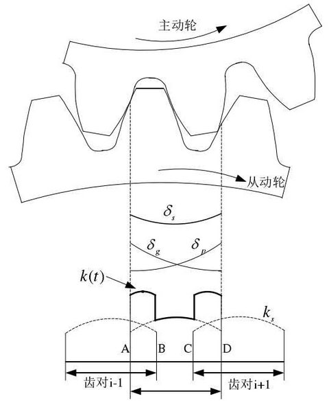
In the process of transmission of motion and power, gear teeth will have bending deformation, shear deformation and other elastic deformation, and the ability of a single tooth pair to resist these elastic deformation becomes single tooth meshing stiffness. The comprehensive meshing stiffness of gear tooth refers to the comprehensive effect of gear tooth stiffness in the whole gear meshing area (AD section in Figure 1), which is mainly related to the material of gear and the number of meshing teeth.

And δ P and δ g in Fig. 1 represent the deformation curves of the driving and driven wheels in the whole process of a single gear tooth from meshing in to meshing out. It can be seen from the figure that the driving wheel enters into the meshing (point a) from the tooth root, so the deformation P is smaller than δ P, and the deformation of the driven wheel starting from the top of the tooth is larger than that of δ G. On the contrary, the amount of deformation δ P of the driving wheel is larger than that of the driving wheel starting from the top of the tooth (point d), while the deformation of the driven wheel is smaller than that of the starting gear from the tooth root.
The sum of elastic deformation of a pair of meshed teeth at each meshing moment in the whole process from the initial engagement to the complete withdrawal of engagement is called the comprehensive deformation of single tooth pair, which is represented by s table δ s

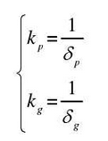
Then the comprehensive meshing stiffness of single tooth pair is expressed as follows:

Where and KP and table kg represent the single tooth stiffness of the driving and driven gears

As shown in Fig. 1, the composite meshing stiffness K (T) is formed by the superposition of the combined meshing stiffness of the tooth pair and single tooth pair at a certain meshing moment. Because the coincidence degree of spur gear is generally between 1-2, the spur gear transmission is an alternating process of single tooth meshing and double tooth meshing. As shown in Fig. 1, AB and CD are single tooth meshing area, and BC period is double tooth meshing area. Since the single tooth meshing area is only loaded by a single pair of meshing teeth, the deformation is large and the meshing stiffness is small. In the double tooth meshing area, the load is shared by two meshing teeth pairs, so the deformation is small and the meshing stiffness is large. At the transition point (point B and point C) of single tooth meshing area and double tooth meshing area, the composite meshing stiffness will appear obvious step phenomenon, which is also the remarkable characteristic of spur gear time-varying meshing stiffness.
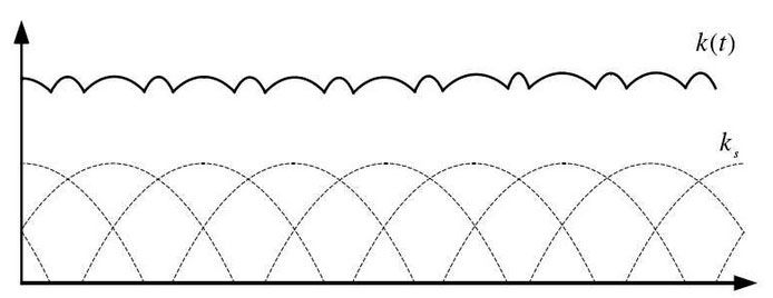
However, the coincidence degree of helical gear is generally larger than 2, and the number of teeth engaged in meshing at the same time is greater than 2, and each meshing tooth pair of helical gear gradually enters into and gradually withdraws from meshing. Therefore, there is no obvious step phenomenon in the comprehensive meshing stiffness, and the fluctuation is relatively gentle. This is also an important reason why the vibration of helical gear transmission is generally less than that of spur gear transmission. The formation of helical gear comprehensive meshing stiffness is shown in Fig. 2.

From the above analysis, it can be seen that the comprehensive meshing stiffness of gears is time-varying. The system dynamic excitation caused by the time-varying meshing stiffness in the process of gear meshing is called stiffness excitation, also known as time-varying meshing stiffness excitation. Because the time-varying meshing stiffness is reflected in the dynamic differential equations as the change of elastic force (gear meshing force), the time-varying meshing stiffness excitation can actually be regarded as a kind of parametric excitation, and the vibration problem caused by the time-varying meshing stiffness can also be regarded as a parametric vibration problem.
