In the following three steps, the formula of meshing force of single tooth is derived, which takes into account the deformation of tooth trimming drum and support system.

1) The area of overlapping area without meshing error.
As shown in Fig. 1 (a), the curve of tooth direction drum trimming is a parabola, and its equation is as follows:
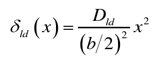
Where, X is the coordinate of any point in the direction of tooth width; DLD is the tooth direction trimming drum; B is the effective tooth width. The formula of overlapping area is as follows:

It can be seen that the overlap area a is determined by the coordinate value of the end point of the parabola (B / 2, DLD) and the normal approach value U.
2) The initial contact position with tooth alignment error.
As shown in Fig. 1 (b), when the meshing tooth direction error of the gear pair is f β y, the tangent point x0 of the straight line L and the parabola is the initial contact position of the two teeth. According to the fact that the slope of the parabola at the tangent point is equal to that of the straight line, the abscissa of the tangent point can be obtained as follows:
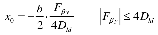
Where, f β y is the meshing tooth direction error, and its value is positive or negative according to the inclination direction of the straight line L; | f β y | ≤ 4dld is the necessary condition to ensure that the tangent point of the straight line and the parabola is within the range of tooth width.
3) The formula of single tooth meshing force of spur gear is obtained by considering both tooth profile modification and meshing error.
Move the origin of the coordinate axis in Fig. 1 (b) to X and rotate the X axis so that it is parallel to the line L to get Fig. 1 (c). Because f β y < B, the rotation angle of the coordinate system is very small. It can be approximately considered that B2 | 2 = B | 2-x0 in Fig. 1 (c), so the coordinates of the endpoint of the parabolic line segment in the new coordinate system are
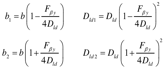
According to the results of the formula, the normal approach u is divided into three parts to calculate the area of the overlap area, taking the ordinates of the two ends of the parabola in Fig. 1 (c) as the boundary

Finally, by multiplying the area of overlapping area and the meshing stiffness of unit tooth width, the formula of single tooth meshing force is obtained, which takes into account the deformation of tooth trimming drum and support system.
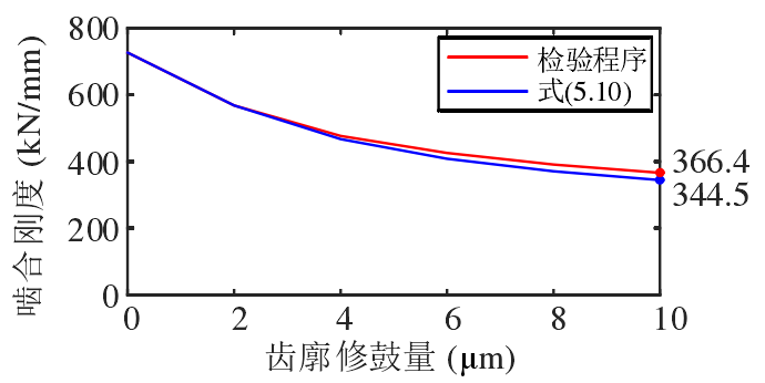
Li calculates the meshing stiffness of different tooth direction under specific load by finite element method, which is used as the standard to verify the correctness of the formula. As shown in Figure 2, the relative error of single tooth meshing stiffness calculated by the formula of single tooth meshing force and finite element method is 6.0% when the amount of tooth profile modification is 10 μ M. It should be pointed out that under the load given by Li, the single tooth deformation of unmodified gear is 2.39 μ m, so 10 μ m is a relatively large amount of tooth direction modification, which indicates that the formula has good accuracy.