
Because reducing the fluctuation of static transmission error is generally accepted as the criterion of tooth profile modification, the key of tooth profile modification is to calculate the static transmission error of gear pair. The traditional sliced gear model is a numerical model, there is a natural contradiction between the calculation accuracy and efficiency. Therefore, this study first deduces a formula of single tooth engagement force based on area calculation, which is a piecewise analytical function.
The gear is divided into several sheet gears with equal width along the tooth width, and each sheet gear is regarded as a spur gear with stiffness Ke = k.be. Where k is the meshing stiffness of unit tooth width line and be is the width of sheet gear. Because the damping force is not considered in the calculation of static transmission error, the total meshing force on the gear tooth is equal to the sum of the elastic forces of each sheet
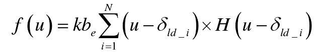
In the formula, n is the number of slice gears divided; H (x) is the Heaviside function, when x ≤ 0, H (x) = 0; when x < 0, H (x) = 1; u is the normal approach of a pair of meshing teeth; δ LD_ I is the profile modification of any slice gear. Some symbols are shown in the figure.

When be approaches 0,
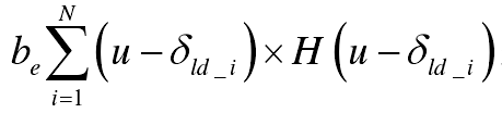
Shows the area of the overlapping area a in Fig. (b). Therefore, the calculation of meshing force under quasi-static condition is simplified to the calculation of overlapping area.