
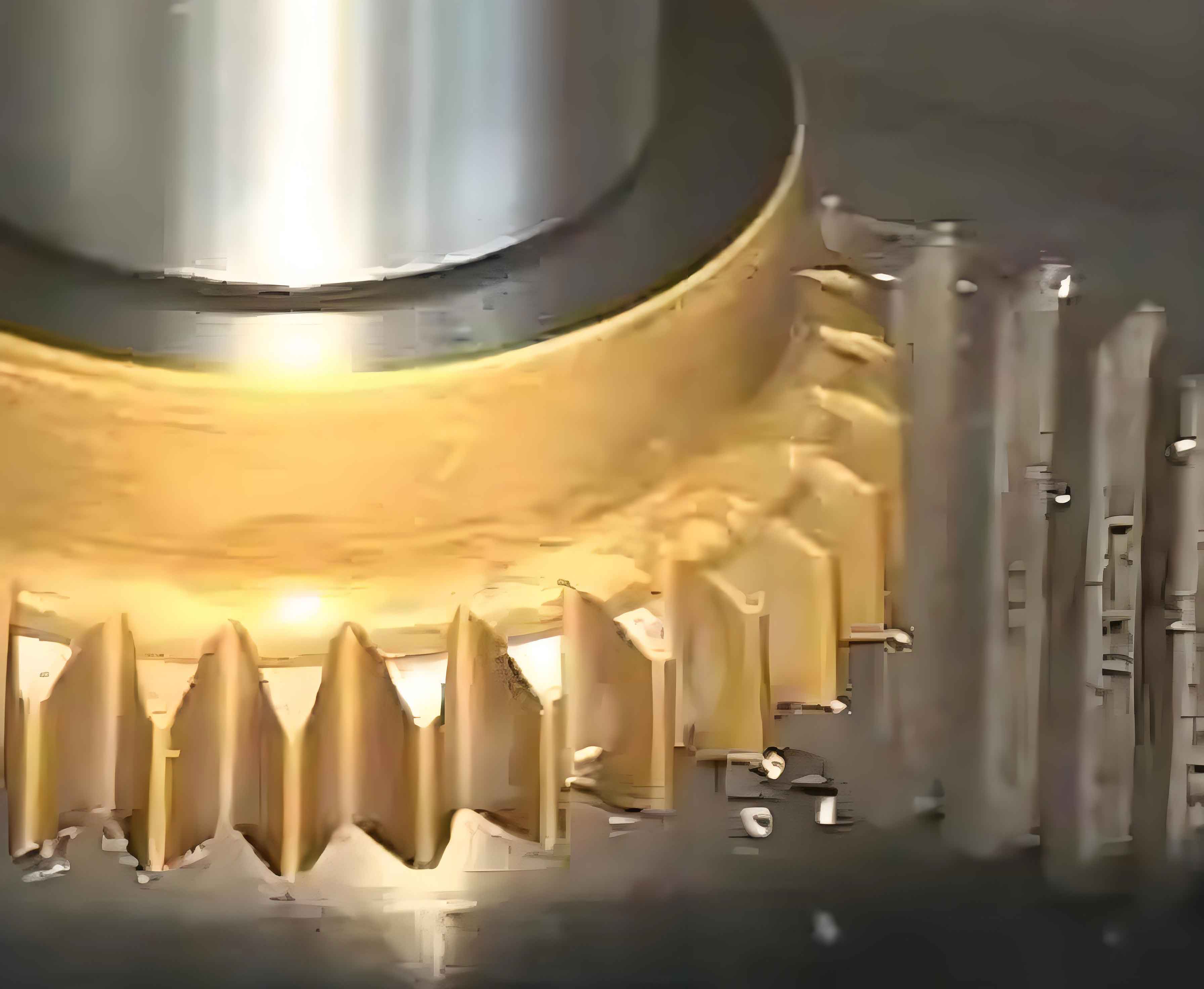
Non-circular gears represent an advanced transmission component combining structural compactness with variable-ratio capabilities, extensively applied in printing machinery, automation systems, flow meters, and hydraulic motors. Their irregular geometries—where each tooth differs—present significant manufacturing challenges. Among prevalent gear shaping methods, CNC gear shaping delivers superior precision, efficiency, and adaptability. Traditional three-axis gear shaping faces interference risks during radial retraction, reducing productivity. Four-axis linkage CNC gear shaping overcomes this through normal or oblique retraction strategies, enhancing flexibility. This work establishes a virtual manufacturing platform using VERICUT to simulate four-axis gear shaping processes, eliminating physical trials and accelerating production cycles.
Gear Shaping Principles and Tooth Surface Modeling
Gear shaping involves the generating motion where a cutter’s pitch circle rolls purely along the gear’s pitch curve. For non-circular gears with pitch curve radius \( r \) defined by:
$$ r = \frac{A(1 – k^2)}{1 – k \cos \phi} $$
where \( A \) is the semi-major axis and \( k \) the eccentricity. The process requires six synchronized motions:
- Primary cutting motion (cutter reciprocation along Z-axis)
- Cutter circumferential feed (rotation about C2-axis)
- Indexing motion (workpiece rotation about C1-axis)
- Position adjustment (X/Y-axis translation)
- Depth-wise feed (radial infeed)
- Retraction motion (normal to pitch curve)
Tooth profiles are derived via the envelope method. For points above the pitch curve, right-flank coordinates are:
$$ \begin{cases} x_R = r_g \cos \theta + a_n \cos(\theta – \mu + \alpha_\mu) \\ y_R = r_g \sin \theta + a_n \sin(\theta – \mu + \alpha_\mu) \end{cases} $$
Left-flank coordinates are:
$$ \begin{cases} x_L = r_g \cos \theta + a’_n \cos(\mu – \theta + \alpha_\mu) \\ y_L = r_g \sin \theta + a’_n \sin(\mu – \theta + \alpha_\mu) \end{cases} $$
Below the pitch curve, equations adjust based on normal vector orientation. This defines the complete 3D tooth surface for theoretical modeling.
Four-Axis Gear Shaping Simulation Methodology
Machine Tool and Component Modeling
A four-axis CNC gear shaping machine model was constructed in Creo, comprising:
| Component | Function | Export Format |
|---|---|---|
| Machine Structure | Kinematic chain simulation | STL assembly |
| Gear Shaping Cutter | Profile generation | Parametric STL |
| Gear Blank | Pitch curve offset geometry | STL contour |
Components were imported into VERICUT’s project tree with kinematic dependencies matching physical axis relationships (X, Y, Z, C1, C2).
Toolpath Generation and NC Programming
Using an equal-arc-length segmentation strategy, the pitch curve was discretized into micro-segments. Corresponding rotation angles for cutter and workpiece were solved via MATLAB, governed by:
$$ s = \int_{\phi_i}^{\phi_{i+1}} r d\phi = r_c \cdot \Delta \theta_c $$
where \( s \) is arc length, \( r_c \) cutter pitch radius, and \( \Delta \theta_c \) cutter rotation increment. Coordinates were output as G-code for SINUMERIK 840D control. Key NC commands included:
- Cutter reciprocation:
G01 Z[position] F[feed] - Synchronized rotation:
C1=[angle] C2=[angle] - Normal retraction:
X[position] Y[position]
Dynamic Simulation Process
VERICUT simulated material removal by resolving cutter-workpiece engagements across 53 teeth. Collision detection confirmed interference-free toolpaths during multi-axis gear shaping. The virtual machining sequence comprised:
- Approach to start position
- Depth-wise infeed to full tooth depth
- Synchronized generating motion with normal retraction
- Indexing to next tooth space
Simulation Validation and Error Analysis
The simulated gear was compared against the design model using VERICUT’s AUTO-DIFF module. Dimensional tolerances were evaluated through chromatic mapping:
| Deviation Type | Max Magnitude (mm) | Affected Regions |
|---|---|---|
| Excess Material | 0.025 | Root fillets |
| Under-Cut | 0.018 | Flank transitions |
Error distribution satisfied ISO 1328 Class 7 tolerance limits, confirming process validity. Four-axis gear shaping eliminated undercuts observed in three-axis strategies, demonstrating superior kinematic flexibility.
Conclusion
This work established a virtual four-axis CNC gear shaping platform using VERICUT, accurately simulating non-circular gear production. Key achievements include:
- Mathematical derivation of non-circular tooth profiles under generating motion constraints
- Development of a digital twin for four-axis gear shaping machines
- Optimized NC programming via equal-arc-length segmentation
- Validation through automated deviation analysis (±0.025mm)
The methodology eliminates physical trials, reduces costs by ~40%, and shortens development cycles by 60%. Future work will integrate real-time cutting force prediction to optimize gear shaping parameters for hardened materials.