40Cr steel gear shaft is the transmission part of small mechanical equipment. Because the gear shaft must bear large torque and friction force in service, the whole gear shaft is tempered and quenched at high frequency to ensure the strength, toughness and wear resistance of the product. But in the process of using, the quality accident of early fracture occurs in the gear teeth, and the rate of fracture scrap is over 30%. In order to find out the reason of 40Cr steel tooth fracture, the author analyzes and discusses the method of macro examination, chemical composition analysis and metallographic examination, so as to improve the quality of 40Cr steel tooth shaft and reduce the occurrence of accidents.
1. Macro inspection
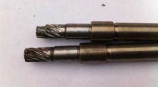
The cracking of 40Cr steel gear shaft is located at the root of the gear with the largest bearing capacity, and extends from the root to the center. The severe crack is about half of the total length of the gear teeth, and the fracture is roughly parallel to the axial direction of the gear shaft (Fig. 1).
2. Chemical composition analysis
From the same batch of raw materials of the fractured gear shaft, cut the sample with the size of < ф 25mm × 15mm, and use the labspark 5000 precision direct reading spark spectrometer to test its chemical composition [1]. The results are shown in Table 1. It can be seen that the chemical composition of the raw material meets the requirements of GB / t3077-1999 alloy structural steel for 40Cr steel composition.
3. Metallographic examination
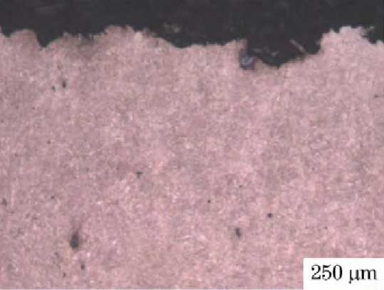
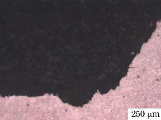
According to the metallographic examination of the fractured gear shaft, the fracture surface of the crack initiation part of the gear shaft is characterized by zigzag and uneven intergranular brittle fracture (Fig. 2). There are black granular holes in the pits and nearby structures of the fracture, which are intergranular cavities of non-metallic inclusions [2], indicating that the heating temperature of the workpiece is too high during the processing. In the final fracture area of the tooth axis crack, the fracture morphology changes to the characteristic morphology of transgranular fracture, and there is still intergranular cave structure near the fracture (Fig. 3).
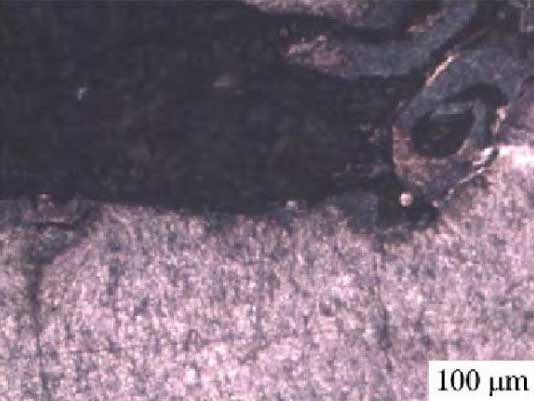
Observe the micro morphology of the cutting surface of the tooth profile (Fig. 4). The micro crack on the left side of the surface is located at the bottom of a grain cracked along the grain, and the right side of the surface is the iron chips curled during cutting, and the whole grain is pulled up. The material has a very serious tendency of embrittlement, and the micro crack with stress concentration cracking is produced along the grain falling off pit. There are many machining tool marks on the surface of gear teeth. On the left and right sides of the cutting surface, quenching stress concentration cracks are found at the bottom of the cutting tool mark (Fig. 5).
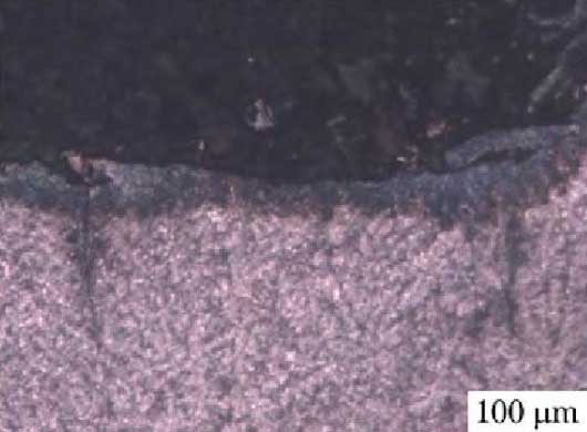
There is a large non-metallic inclusion in the sub surface layer of gear tooth machining surface, and the crack propagates from the inclusion to both sides. A crack extending to the surface layer happens to divide the curled iron chips machined on the surface into two parts (Fig. 6). At the bottom of the gear teeth, there is obvious fibrous structure with large deformation, which is caused by too much cutting or too blunt tool. Extrusion caused by deformation causes multiple brittle cracks at the bottom of the whole gear, and secondary quenching stress concentration causes cracks at the brittle cracks of the deformed structure (Fig. 7).
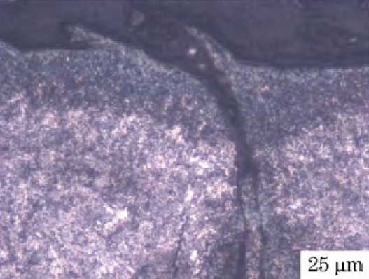
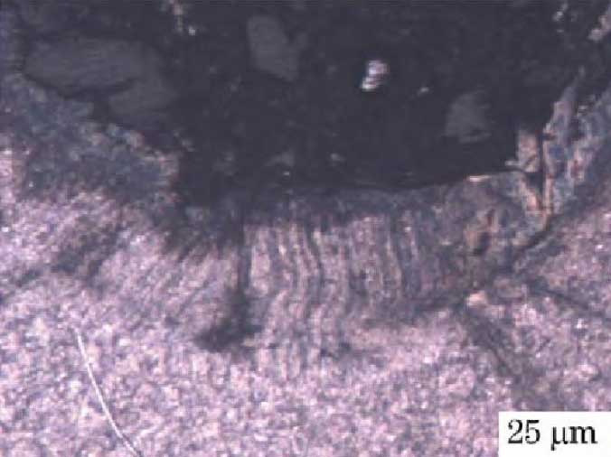
According to the evaluation standard of GB / T 13298-1991 test method of metal microstructure, the band structure grade is above 3, which can be determined that the number of band structure before tempering and high-frequency quenching treatment is more. The excessive banded structure greatly reduces the transverse tensile strength of the material and increases the brittleness of the material (Fig. 8, 9).
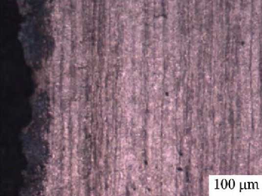
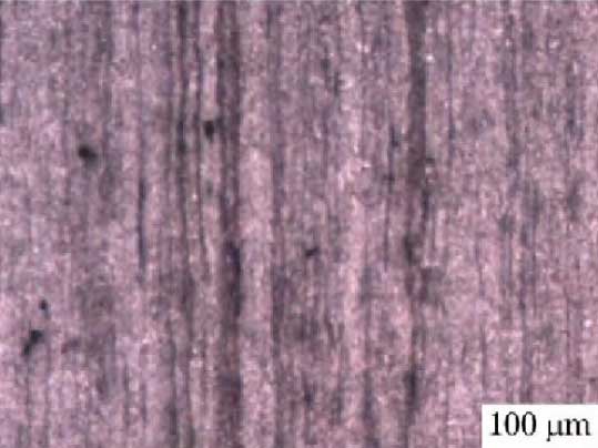
Through the high magnification observation of the banded structure, it can be seen that the banded structure has a wide band, and there are many light gray non-metallic inclusions between the bands, which belong to the sulfide inclusions with low melting point and low strength. The banded structure and inclusions destroy the continuity of the matrix and significantly reduce the tensile strength of the material (FIG. 10). Through metallographic observation of cross section, it can be seen that the structure is coarse grain, which is caused by high forging and rolling temperature (FIG. 11).
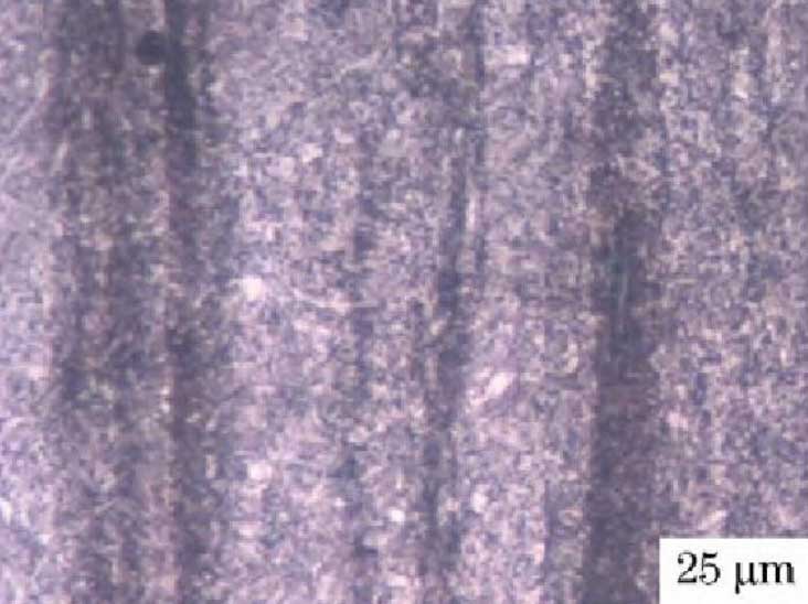
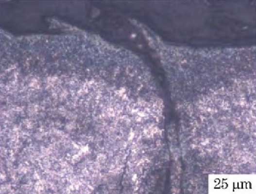
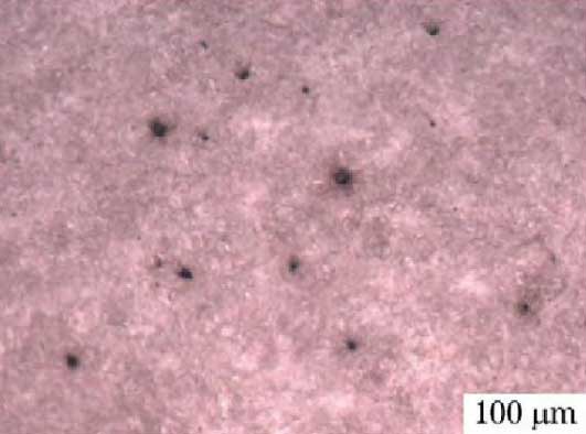
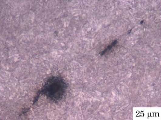
In the matrix structure of the material, there are a large number of black intergranular caves and long low melting point sulfide inclusions, which greatly reduce the structure and properties of the material (Fig. 12, 13).
In the process of tooth profile cutting of gear shaft, the surface of gear teeth will be covered and curled by iron chips due to too large cutting depth or too blunt cutting tool, the surface grains will fall off, and even the extrusion microcracks will be caused by large deformation, and many factors will form the quenching stress concentration, resulting in the cracks [6]. At the same time, there are too many non-metallic inclusions in the raw material, and the amount of banded structure formed by them is more, the strength of the material decreases and the brittleness increases. The rolling temperature of the material is too high, which has formed the overheated coarse structure, even the intergranular cave structure with the characteristics of overburning. The strength of the material is further reduced, and the brittleness is further increased.
The tooth surface and root of the gear shaft have cracks before use. When the parts are in service, the quenching cracks continue to expand under the working stress. The low strength and high brittleness of the defective structure of the raw material significantly reduce the tensile strength of the material, which eventually leads to the fracture failure of the gear teeth of the gear shaft.
