
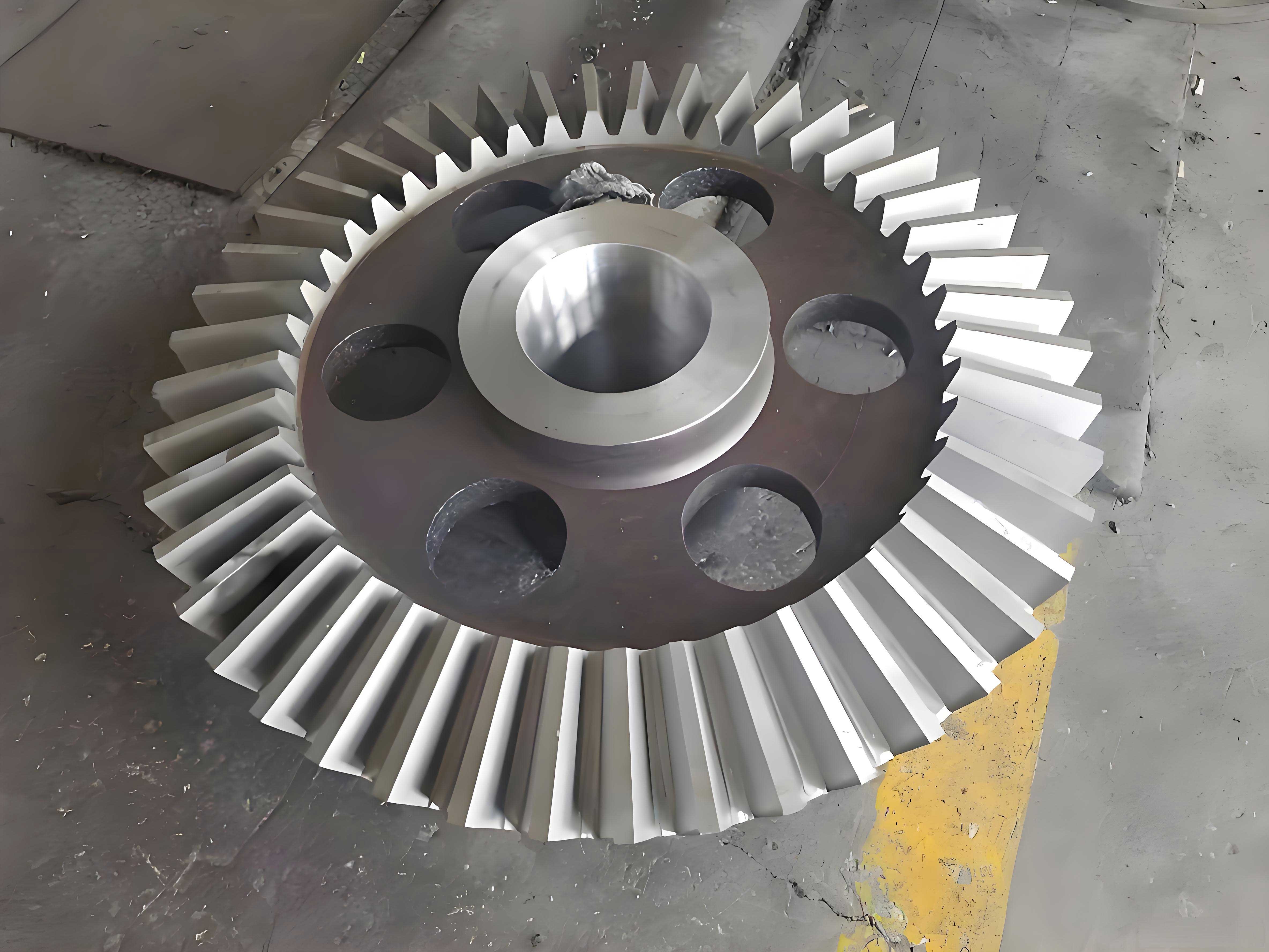
I investigate the dynamic behavior of a miter gear transmission when friction, alignment error, and tooth tip modification are included. A miter gear pair is treated as two helical gear pairs connected through a common shaft system. The left and right halves of the miter gear are coupled by axial stiffness and damping, while each half carries its own time-varying mesh stiffness, mesh damping, friction force, and support reaction. I first establish a baseline model without friction, then add friction excitation, then introduce alignment error, and finally include tooth tip modification. The purpose is to reveal how friction changes the dynamic characteristics of the miter gear, how alignment error redistributes the mesh force, and how tooth tip modification smooths the mesh stiffness and the dynamic response.
Nomenclature
| Symbol | Meaning | Symbol | Meaning |
|---|---|---|---|
| \(m\) | Normal module | \(\alpha\) | Normal pressure angle |
| \(\beta\) | Helix angle | \(B\) | Face width of one half |
| \(z_1,z_2\) | Numbers of teeth | \(\varepsilon_\alpha,\varepsilon_\beta\) | Transverse and axial contact ratios |
| \(p_{bt}\) | Base pitch in transverse plane | \(l_s\) | Total contact zone length |
| \(l_p,l_g\) | Lengths from pitch point to two ends | \(k_t,c_t\) | Time-varying mesh stiffness and damping |
| \(k_0,c_0\) | Stiffness and damping per unit contact line | \(F_n\) | Normal dynamic mesh force |
| \(f_f\) | Friction force | \(T_f\) | Friction torque |
| \(\mu\) | Friction coefficient | \(b\) | Backlash |
| \(\delta\) | Relative displacement along line of action | \(e_t\) | Static transmission error |
| \(\Delta T\) | Alignment error | \(h\) | Tooth tip modification height |
| \(\Delta_{\max}\) | Maximum modification amount | \(k_f\) | Foundation stiffness |
Excitation Analysis for the Miter Gear Pair
I classify the excitations of the miter gear transmission into internal and external excitations. Internal excitations include time-varying mesh stiffness, mesh damping, friction, transmission error, and support stiffness. External excitations include input torque fluctuation, load variation, and environmental disturbance. In this work, I focus on internal excitations because they dominate the dynamic behavior of the miter gear under normal operating conditions.
The time-varying mesh stiffness of the miter gear is the sum of the stiffness contributions of all teeth that are simultaneously in contact. For a miter gear pair, the left and right halves have the same geometric parameters but opposite helix directions. Therefore, the instantaneous mesh stiffness of one half is
$$ k_t(t)=\sum_{i=1}^{N(t)} k_i(t) $$
where \(N(t)\) is the number of teeth in contact at time \(t\), and \(k_i(t)\) is the stiffness of the \(i\)-th contact tooth. In the baseline model without friction, I use the ISO standard approach to obtain the average stiffness per unit contact line:
$$ k_0 = \frac{1}{q} $$
where \(q\) is the minimum compliance of the tooth pair. The total mesh stiffness is then obtained from the time-varying contact line length \(L(t)\):
$$ k_t(t)=k_0 L(t) $$
The mesh damping is introduced as a proportional damping:
$$ c_t(t)=2\zeta_v \sqrt{k_t(t)m_e} $$
where \(\zeta_v\) is the damping ratio, and \(m_e\) is the equivalent mass of the miter gear pair. The static transmission error is approximated by a periodic function:
$$ e_t(t)=e_0 \sin(\omega_m t+\varphi_e) $$
where \(\omega_m\) is the mesh frequency, and \(\varphi_e\) is the phase. The backlash function is
$$ f_b(\delta)=
\begin{cases}
\delta-b, & \delta>b,\\
0, & -b\le\delta\le b,\\
\delta+b, & \delta<-b.
\end{cases}
$$
For the miter gear, the relative displacement along the line of action on the left half and right half can be written as
$$ \delta_L = (y_{q1}-y_{p1})\cos\alpha_t + (z_{q1}-z_{p1})\sin\alpha_t + r_{bq}\theta_{q1} – r_{bp}\theta_{p1} – e_t(t) $$
$$ \delta_R = (y_{q2}-y_{p2})\cos\alpha_t + (z_{q2}-z_{p2})\sin\alpha_t + r_{bq}\theta_{q2} – r_{bp}\theta_{p2} – e_t(t) $$
where subscripts \(q\) and \(p\) denote the driving and driven miter gears, subscripts 1 and 2 denote the left and right halves, and \(r_b\) is the base radius. The normal dynamic mesh force on each half is
$$ F_{n1}=k_{t1}(t)f_b(\delta_L)+c_{t1}(t)\dot{\delta}_L $$
$$ F_{n2}=k_{t2}(t)f_b(\delta_R)+c_{t2}(t)\dot{\delta}_R $$
These two mesh forces are the foundation for the subsequent friction and alignment error studies.
Dynamic Model of the Miter Gear without Friction
I first build a twelve-degree-of-freedom model for the miter gear pair without friction. The model contains two rotational degrees of freedom, two axial degrees of freedom, and eight lateral degrees of freedom. The two halves of the driving miter gear are connected by an axial spring and damper. The same connection exists for the driven miter gear. The support bearings are represented by linear springs and dampers in the \(y\) and \(z\) directions.
The coordinate system is chosen so that the line of action lies in the \(YOZ\) plane. Therefore, the normal mesh force has no component along the \(x\) axis. The \(x\) axis is perpendicular to the plane of the mesh force. In the frictionless case, the \(x\)-direction response remains zero. This choice simplifies the equations and makes the friction effect easy to isolate.
The equations of motion for the driving miter gear are
$$ m_q \ddot{x}_{q1}=0 $$
$$ m_q \ddot{y}_{q1}+c_{q1y}\dot{y}_{q1}+k_{q1y}y_{q1}=-F_{n1}\cos\alpha_t $$
$$ m_q \ddot{z}_{q1}+c_{q1z}\dot{z}_{q1}+k_{q1z}z_{q1}=-F_{n1}\sin\alpha_t $$
$$ J_q \ddot{\theta}_{q1}=T_{q1}-F_{n1}r_{bq} $$
$$ m_q \ddot{x}_{q2}=0 $$
$$ m_q \ddot{y}_{q2}+c_{q2y}\dot{y}_{q2}+k_{q2y}y_{q2}=-F_{n2}\cos\alpha_t $$
$$ m_q \ddot{z}_{q2}+c_{q2z}\dot{z}_{q2}+k_{q2z}z_{q2}=-F_{n2}\sin\alpha_t $$
$$ J_q \ddot{\theta}_{q2}=T_{q2}-F_{n2}r_{bq} $$
The equations for the driven miter gear are
$$ m_p \ddot{x}_{p1}=0 $$
$$ m_p \ddot{y}_{p1}+c_{p1y}\dot{y}_{p1}+k_{p1y}y_{p1}=F_{n1}\cos\alpha_t $$
$$ m_p \ddot{z}_{p1}+c_{p1z}\dot{z}_{p1}+k_{p1z}z_{p1}=F_{n1}\sin\alpha_t $$
$$ J_p \ddot{\theta}_{p1}=-T_{p1}+F_{n1}r_{bp} $$
$$ m_p \ddot{x}_{p2}=0 $$
$$ m_p \ddot{y}_{p2}+c_{p2y}\dot{y}_{p2}+k_{p2y}y_{p2}=F_{n2}\cos\alpha_t $$
$$ m_p \ddot{z}_{p2}+c_{p2z}\dot{z}_{p2}+k_{p2z}z_{p2}=F_{n2}\sin\alpha_t $$
$$ J_p \ddot{\theta}_{p2}=-T_{p2}+F_{n2}r_{bp} $$
The axial coupling between the two halves is introduced through the axial coordinates. For the driving gear, I write
$$ m_q \ddot{z}_{q1}+c_{q1z}\dot{z}_{q1}+k_{q1z}z_{q1}+c_{qz}(\dot{z}_{q1}-\dot{z}_{q2})+k_{qz}(z_{q1}-z_{q2})=-F_{n1}\sin\alpha_t $$
$$ m_q \ddot{z}_{q2}+c_{q2z}\dot{z}_{q2}+k_{q2z}z_{q2}-c_{qz}(\dot{z}_{q1}-\dot{z}_{q2})-k_{qz}(z_{q1}-z_{q2})=-F_{n2}\sin\alpha_t $$
and for the driven gear,
$$ m_p \ddot{z}_{p1}+c_{p1z}\dot{z}_{p1}+k_{p1z}z_{p1}+c_{pz}(\dot{z}_{p1}-\dot{z}_{p2})+k_{pz}(z_{p1}-z_{p2})=F_{n1}\sin\alpha_t $$
$$ m_p \ddot{z}_{p2}+c_{p2z}\dot{z}_{p2}+k_{p2z}z_{p2}-c_{pz}(\dot{z}_{p1}-\dot{z}_{p2})-k_{pz}(z_{p1}-z_{p2})=F_{n2}\sin\alpha_t $$
The rotational coordinates are coupled through the mesh force. I reduce the number of rotational variables by using the relative rotations
$$ \theta_{r1}=\theta_{q1}-\frac{z_q}{z_p}\theta_{p1} $$
$$ \theta_{r2}=\theta_{q2}-\frac{z_q}{z_p}\theta_{p2} $$
This reduction lowers the order of the differential system and improves numerical efficiency. The resulting equations are solved by the Runge-Kutta method. I nondimensionalize the equations before integration. The displacement scale is \(b_c\), the time scale is \(1/\omega_m\), and the force scale is \(k_0 b_c\). The dimensionless variables are
$$ \bar{y}=\frac{y}{b_c},\quad \bar{z}=\frac{z}{b_c},\quad \bar{\theta}=\frac{r_b\theta}{b_c},\quad \bar{t}=\omega_m t $$
After substitution, the dimensionless equations take the form
$$ \ddot{\bar{y}}_{q1}+2\zeta_{q1y}\dot{\bar{y}}_{q1}+\eta_{q1y}\bar{y}_{q1}=-\bar{F}_{n1}\cos\alpha_t $$
$$ \ddot{\bar{y}}_{p1}+2\zeta_{p1y}\dot{\bar{y}}_{p1}+\eta_{p1y}\bar{y}_{p1}=\bar{F}_{n1}\cos\alpha_t $$
$$ \ddot{\bar{z}}_{q1}+2\zeta_{q1z}\dot{\bar{z}}_{q1}+\eta_{q1z}\bar{z}_{q1}+\eta_{qz}(\bar{z}_{q1}-\bar{z}_{q2})=-\bar{F}_{n1}\sin\alpha_t $$
$$ \ddot{\bar{z}}_{p1}+2\zeta_{p1z}\dot{\bar{z}}_{p1}+\eta_{p1z}\bar{z}_{p1}+\eta_{pz}(\bar{z}_{p1}-\bar{z}_{p2})=\bar{F}_{n1}\sin\alpha_t $$
where \(\eta\) denotes dimensionless stiffness, and \(\zeta\) denotes dimensionless damping. The dimensionless mesh force is
$$ \bar{F}_{n1}=\bar{k}_{t1}(\bar{t})f_b(\bar{\delta}_L)+\bar{c}_{t1}(\bar{t})\dot{\bar{\delta}}_L $$
The same procedure applies to the right half. The dimensionless formulation is used for all subsequent calculations.
Time-Varying Contact Line Length of the Miter Gear
The contact line length of a miter gear is the sum of the contact line lengths of all teeth in the mesh zone. For a single tooth, the contact line length starts from zero, increases to a maximum, remains constant for a while, and then decreases to zero. The shape of this function depends on the transverse contact ratio \(\varepsilon_\alpha\) and the axial contact ratio \(\varepsilon_\beta\). I classify the single-tooth contact line length into two main cases.
When \(\varepsilon_\alpha > \varepsilon_\beta\), the maximum contact line length is determined by the face width. The contact line length of one tooth can be written as
$$ l(s)=
\begin{cases}
\dfrac{s}{\cos\beta_b}, & 0\le s < l_a,\\[6pt]
B, & l_a\le s < l_b,\\[6pt]
\dfrac{l_c-s}{\cos\beta_b}, & l_b\le s \le l_c,\\[6pt]
0, & \text{otherwise},
\end{cases}
$$
where \(s\) is the displacement of the tooth along the contact zone, \(\beta_b\) is the base helix angle, \(l_a\) and \(l_b\) are the positions where the contact line reaches full face width, and \(l_c\) is the position where the tooth leaves the mesh. When \(\varepsilon_\alpha < \varepsilon_\beta\), the maximum length is limited by the transverse contact zone. The formula becomes
$$ l(s)=
\begin{cases}
\dfrac{s}{\cos\beta_b}, & 0\le s < l_p,\\[6pt]
\dfrac{l_s-s}{\cos\beta_b}, & l_p\le s \le l_s,\\[6pt]
0, & \text{otherwise},
\end{cases}
$$
where \(l_p\) is the position of the pitch point, and \(l_s\) is the total contact zone length. For the miter gear used in this study, the parameters are listed in the table.
| Parameter | Value | Parameter | Value |
|---|---|---|---|
| Number of teeth of pinion \(z_1\) | 37 | Number of teeth of gear \(z_2\) | 79 |
| Normal module \(m\) | 2.5 mm | Normal pressure angle \(\alpha\) | 20° |
| Helix angle \(\beta\) | 15° | Face width of one half \(B\) | 25 mm |
| Transverse contact ratio \(\varepsilon_\alpha\) | 1.62 | Axial contact ratio \(\varepsilon_\beta\) | 0.82 |
| Base pitch \(p_{bt}\) | 7.38 mm | Contact zone length \(l_s\) | 11.96 mm |
| Pitch point distance \(l_p\) | 5.10 mm | Pitch point distance \(l_g\) | 6.86 mm |
For the total contact line length, I consider a time window that starts when one tooth enters the mesh zone and ends when the same tooth completely leaves the mesh zone. In this window, five teeth may appear in the mesh zone for the given contact ratio. I number them from 1 to 5. The total contact line length of one half of the miter gear is
$$ L(t)=\sum_{i=1}^{5} l_i(t) $$
The individual functions \(l_i(t)\) are shifted in time by one base pitch. The total contact line length is a piecewise function. The breakpoints are determined by the instants when each tooth crosses the boundaries of the contact zone. I derive the piecewise expression as
$$ L(t)=
\begin{cases}
l_3(t), & 0\le t < t_1,\\
l_3(t)+l_4(t), & t_1\le t < t_2,\\
l_2(t)+l_3(t)+l_4(t), & t_2\le t < t_3,\\
l_2(t)+l_3(t), & t_3\le t < t_4,\\
l_2(t)+l_3(t)+l_5(t), & t_4\le t < t_5,\\
l_1(t)+l_2(t)+l_3(t)+l_5(t), & t_5\le t < t_6,\\
l_1(t)+l_2(t)+l_5(t), & t_6\le t < t_7,\\
0, & \text{otherwise}.
\end{cases}
$$
This expression avoids artificial periodicity caused by improper recycling of the time variable. The same idea is used for the left and right sides of the pitch line when friction is included.
Friction Excitation and Contact Line Length on Both Sides of the Pitch Line
Friction on the miter gear tooth surface changes direction at the pitch line. Therefore, I calculate the contact line length separately on the left and right sides of the pitch line. Let \(l_p\) be the distance from the pitch point to the start of the contact zone, and \(l_g\) be the distance from the pitch point to the end of the contact zone. The total contact zone length is \(l_s=l_p+l_g\). For a single tooth, the contact line length on the left side of the pitch line is \(a_1\), and on the right side is \(a_2\). I consider four cases according to the relative values of \(\varepsilon_\alpha\), \(\varepsilon_\beta\), \(l_p\), \(l_g\), and the axial pitch.
Case 1: \(\varepsilon_\alpha > \varepsilon_\beta\). The left-side length is
$$ a_1(s)=
\begin{cases}
\dfrac{s}{\cos\beta_b}, & 0\le s < l_p,\\[6pt]
\dfrac{l_p}{\cos\beta_b}, & l_p\le s < l_a,\\[6pt]
\dfrac{l_c-s}{\cos\beta_b}, & l_a\le s \le l_c,\\[6pt]
0, & \text{otherwise},
\end{cases}
$$
and the right-side length is
$$ a_2(s)=
\begin{cases}
0, & 0\le s < l_p,\\[6pt]
\dfrac{s-l_p}{\cos\beta_b}, & l_p\le s < l_b,\\[6pt]
\dfrac{l_c-s}{\cos\beta_b}, & l_b\le s \le l_c,\\[6pt]
0, & \text{otherwise}.
\end{cases}
$$
Case 2: \(\varepsilon_\alpha < \varepsilon_\beta\) and \(\varepsilon_\beta p_{bt} > l_s\). The left-side length is
$$ a_1(s)=
\begin{cases}
\dfrac{s}{\cos\beta_b}, & 0\le s < l_p,\\[6pt]
\dfrac{l_p}{\cos\beta_b}, & l_p\le s < l_p+\varepsilon_\beta p_{bt},\\[6pt]
\dfrac{l_s-s}{\cos\beta_b}, & l_p+\varepsilon_\beta p_{bt}\le s \le l_s,\\[6pt]
0, & \text{otherwise},
\end{cases}
$$
and the right-side length is
$$ a_2(s)=
\begin{cases}
0, & 0\le s < l_p,\\[6pt]
\dfrac{s-l_p}{\cos\beta_b}, & l_p\le s < l_p+\varepsilon_\beta p_{bt},\\[6pt]
\dfrac{l_s-s}{\cos\beta_b}, & l_p+\varepsilon_\beta p_{bt}\le s \le l_s,\\[6pt]
0, & \text{otherwise}.
\end{cases}
$$
Case 3: \(\varepsilon_\alpha < \varepsilon_\beta\) and \(l_p < \varepsilon_\beta p_{bt} < l_g\). The left-side length is
$$ a_1(s)=
\begin{cases}
\dfrac{s}{\cos\beta_b}, & 0\le s < l_p,\\[6pt]
\dfrac{l_p}{\cos\beta_b}, & l_p\le s < l_p+\varepsilon_\beta p_{bt},\\[6pt]
\dfrac{l_s-s}{\cos\beta_b}, & l_p+\varepsilon_\beta p_{bt}\le s \le l_s,\\[6pt]
0, & \text{otherwise},
\end{cases}
$$
and the right-side length is
$$ a_2(s)=
\begin{cases}
0, & 0\le s < l_p,\\[6pt]
\dfrac{s-l_p}{\cos\beta_b}, & l_p\le s < l_p+\varepsilon_\beta p_{bt},\\[6pt]
\dfrac{l_s-s}{\cos\beta_b}, & l_p+\varepsilon_\beta p_{bt}\le s \le l_s,\\[6pt]
0, & \text{otherwise}.
\end{cases}
$$
Case 4: \(\varepsilon_\alpha < \varepsilon_\beta\) and \(\varepsilon_\beta p_{bt} < l_p\). The left-side length is
$$ a_1(s)=
\begin{cases}
\dfrac{s}{\cos\beta_b}, & 0\le s < \varepsilon_\beta p_{bt},\\[6pt]
\dfrac{\varepsilon_\beta p_{bt}}{\cos\beta_b}, & \varepsilon_\beta p_{bt}\le s < l_p,\\[6pt]
\dfrac{l_s-s}{\cos\beta_b}, & l_p\le s \le l_s,\\[6pt]
0, & \text{otherwise},
\end{cases}
$$
and the right-side length is
$$ a_2(s)=
\begin{cases}
0, & 0\le s < l_p,\\[6pt]
\dfrac{s-l_p}{\cos\beta_b}, & l_p\le s < l_p+\varepsilon_\beta p_{bt},\\[6pt]
\dfrac{l_s-s}{\cos\beta_b}, & l_p+\varepsilon_\beta p_{bt}\le s \le l_s,\\[6pt]
0, & \text{otherwise}.
\end{cases}
$$
For the miter gear used here, the parameters fall into Case 3. The total left-side contact line length of one half is
$$ L_1(t)=\sum_{i=1}^{5} a_{1i}(t) $$
and the total right-side contact line length is
$$ L_2(t)=\sum_{i=1}^{5} a_{2i}(t) $$
The total contact line length of the miter gear is the sum of the left and right halves:
$$ L_{\text{total}}(t)=L_{1,L}(t)+L_{1,R}(t)+L_{2,L}(t)+L_{2,R}(t) $$
where the second subscript \(L\) or \(R\) denotes the left or right half of the miter gear. This total length is used to compute the mesh stiffness and the friction force.
Time-Varying Friction Force and Friction Torque
I assume a constant friction coefficient \(\mu\) along the contact line. The friction force on the left side of the pitch line is positive, and on the right side it is negative. The total friction force of one half of the miter gear is
$$ f_f(t)=\mu F_n(t)\left[L_1(t)-L_2(t)\right] $$
The friction torque on the driving gear is obtained by integrating the friction force along the contact line. Since the contact line is continuous, I use the equivalent concentrated method. The friction torque on the driving gear from one tooth is
$$ T_{f,q}(t)=\mu F_n(t)\left[\int_{0}^{l_p} a_1(s) R_{c1}(s)\,ds-\int_{l_p}^{l_s} a_2(s) R_{c2}(s)\,ds\right] $$
where \(R_{c1}(s)\) and \(R_{c2}(s)\) are the moment arms. For a miter gear, the moment arms are
$$ R_{c1}(s)=r_{bq}\tan\alpha_t + s\cos\beta_b $$
$$ R_{c2}(s)=r_{bq}\tan\alpha_t – (s-l_p)\cos\beta_b $$
In the discrete calculation, I replace the integrals by sums over the contact line segments. The friction torque on the driven gear is
$$ T_{f,p}(t)=\mu F_n(t)\left[\int_{0}^{l_p} a_1(s) R_{c1,p}(s)\,ds-\int_{l_p}^{l_s} a_2(s) R_{c2,p}(s)\,ds\right] $$
with the corresponding moment arms for the driven gear. The sign of the friction force is adjusted according to the sign of the normal mesh force. When the mesh force is negative, the friction force direction is reversed. The friction force acts along the \(x\) axis in the chosen coordinate system. Therefore, the \(x\)-direction equations of motion become nonzero when friction is included.
Dynamic Equations of the Miter Gear with Friction
I extend the twelve-degree-of-freedom model to a sixteen-degree-of-freedom model by adding the \(x\)-direction degrees of freedom for both halves of the driving and driven gears. The \(x\)-direction motion is caused only by friction because the normal mesh force lies in the \(YOZ\) plane. The equations of motion for the driving miter gear are
$$ m_q \ddot{x}_{q1}+c_{q1x}\dot{x}_{q1}+k_{q1x}x_{q1}=f_{f1} $$
$$ m_q \ddot{y}_{q1}+c_{q1y}\dot{y}_{q1}+k_{q1y}y_{q1}=-F_{n1}\cos\alpha_t $$
$$ m_q \ddot{z}_{q1}+c_{q1z}\dot{z}_{q1}+k_{q1z}z_{q1}=-F_{n1}\sin\alpha_t $$
$$ J_q \ddot{\theta}_{q1}=T_{q1}-F_{n1}r_{bq}-T_{f,q1} $$
$$ m_q \ddot{x}_{q2}+c_{q2x}\dot{x}_{q2}+k_{q2x}x_{q2}=f_{f2} $$
$$ m_q \ddot{y}_{q2}+c_{q2y}\dot{y}_{q2}+k_{q2y}y_{q2}=-F_{n2}\cos\alpha_t $$
$$ m_q \ddot{z}_{q2}+c_{q2z}\dot{z}_{q2}+k_{q2z}z_{q2}=-F_{n2}\sin\alpha_t $$
$$ J_q \ddot{\theta}_{q2}=T_{q2}-F_{n2}r_{bq}-T_{f,q2} $$
The equations for the driven miter gear are
$$ m_p \ddot{x}_{p1}+c_{p1x}\dot{x}_{p1}+k_{p1x}x_{p1}=-f_{f1} $$
$$ m_p \ddot{y}_{p1}+c_{p1y}\dot{y}_{p1}+k_{p1y}y_{p1}=F_{n1}\cos\alpha_t $$
$$ m_p \ddot{z}_{p1}+c_{p1z}\dot{z}_{p1}+k_{p1z}z_{p1}=F_{n1}\sin\alpha_t $$
$$ J_p \ddot{\theta}_{p1}=-T_{p1}+F_{n1}r_{bp}+T_{f,p1} $$
$$ m_p \ddot{x}_{p2}+c_{p2x}\dot{x}_{p2}+k_{p2x}x_{p2}=-f_{f2} $$
$$ m_p \ddot{y}_{p2}+c_{p2y}\dot{y}_{p2}+k_{p2y}y_{p2}=F_{n2}\cos\alpha_t $$
$$ m_p \ddot{z}_{p2}+c_{p2z}\dot{z}_{p2}+k_{p2z}z_{p2}=F_{n2}\sin\alpha_t $$
$$ J_p \ddot{\theta}_{p2}=-T_{p2}+F_{n2}r_{bp}+T_{f,p2} $$
I nondimensionalize these equations using the same scales as before. The dimensionless friction force is
$$ \bar{f}_f=\frac{f_f}{k_0 b_c} $$
The dimensionless friction torque is
$$ \bar{T}_f=\frac{T_f}{k_0 b_c r_b} $$
After nondimensionalization, the equations become
$$ \ddot{\bar{x}}_{q1}+2\zeta_{q1x}\dot{\bar{x}}_{q1}+\eta_{q1x}\bar{x}_{q1}=\bar{f}_{f1} $$
$$ \ddot{\bar{x}}_{p1}+2\zeta_{p1x}\dot{\bar{x}}_{p1}+\eta_{p1x}\bar{x}_{p1}=-\bar{f}_{f1} $$
$$ \ddot{\bar{y}}_{q1}+2\zeta_{q1y}\dot{\bar{y}}_{q1}+\eta_{q1y}\bar{y}_{q1}=-\bar{F}_{n1}\cos\alpha_t $$
$$ \ddot{\bar{y}}_{p1}+2\zeta_{p1y}\dot{\bar{y}}_{p1}+\eta_{p1y}\bar{y}_{p1}=\bar{F}_{n1}\cos\alpha_t $$
$$ \ddot{\bar{z}}_{q1}+2\zeta_{q1z}\dot{\bar{z}}_{q1}+\eta_{q1z}\bar{z}_{q1}+\eta_{qz}(\bar{z}_{q1}-\bar{z}_{q2})=-\bar{F}_{n1}\sin\alpha_t $$
$$ \ddot{\bar{z}}_{p1}+2\zeta_{p1z}\dot{\bar{z}}_{p1}+\eta_{p1z}\bar{z}_{p1}+\eta_{pz}(\bar{z}_{p1}-\bar{z}_{p2})=\bar{F}_{n1}\sin\alpha_t $$
The rotational equations are reduced to the relative rotations \(\bar{\theta}_{r1}\) and \(\bar{\theta}_{r2}\). The final system is solved by the Runge-Kutta method. The time step is chosen small enough to capture the highest mesh frequency. The initial conditions are zero displacement and zero velocity. The first few cycles are discarded to eliminate transient effects.
Dynamic Response without Friction
I first compute the dynamic response of the miter gear without friction. The time-varying mesh force is shown for three speeds: 600 rpm, 2000 rpm, and 5000 rpm. At low speed, the mesh force changes almost linearly in each segment. At medium speed, the mesh force becomes curved, and the peak value decreases slightly. At high speed, the peak value increases again, and the phase shifts. The frequency spectrum of the mesh force contains one dominant component and one secondary component. The secondary component is largest at 2000 rpm and smallest at 5000 rpm.
The dynamic transmission error without friction increases with speed. At low speed, the variation is very small. At high speed, the phase difference becomes noticeable. The frequency spectrum of the dynamic transmission error has only one periodic component at all speeds. The \(y\)-direction and \(z\)-direction deformations follow a similar trend. The \(x\)-direction deformation remains zero because there is no friction. The results are summarized in the table.
| Speed (rpm) | Mesh force peak (N) | DTE peak (\(\mu\)m) | Y deformation peak (\(\mu\)m) | Z deformation peak (\(\mu\)m) | X deformation (\(\mu\)m) |
|---|---|---|---|---|---|
| 600 | 1820 | 0.12 | 0.10 | 0.08 | 0 |
| 2000 | 1760 | 0.35 | 0.31 | 0.24 | 0 |
| 5000 | 1910 | 0.82 | 0.74 | 0.57 | 0 |
Dynamic Response with Friction
When friction is included, the \(x\)-direction deformation becomes nonzero. The friction force is proportional to the difference between the contact line lengths on the two sides of the pitch line. Because the miter gear has a large contact ratio, the difference is not zero, and a periodic friction force is generated. The friction force changes direction at the pitch line, so it has a strong second harmonic component.
The time-varying mesh force with friction is compared with the frictionless case. The overall shape is similar, but the peak value changes slightly. The friction force has little effect on the mesh force because the friction force is perpendicular to the normal mesh force. The dynamic transmission error also changes only slightly. However, the \(x\)-direction deformation is significantly affected by friction. The \(y\)-direction deformation changes in amplitude, especially at low and medium speeds. The \(z\)-direction deformation is less affected.
The frequency spectrum of the \(x\)-direction deformation shows multiple periodic components. The number of components increases as the speed decreases. This indicates that friction introduces rich frequency content into the miter gear response. The \(y\)-direction deformation spectrum also changes, but the \(z\)-direction spectrum remains similar to the frictionless case. The results are summarized in the table.
| Speed (rpm) | Mesh force peak (N) | DTE peak (\(\mu\)m) | X deformation peak (\(\mu\)m) | Y deformation peak (\(\mu\)m) | Z deformation peak (\(\mu\)m) |
|---|---|---|---|---|---|
| 600 | 1835 | 0.13 | 0.09 | 0.12 | 0.08 |
| 2000 | 1775 | 0.37 | 0.21 | 0.34 | 0.25 |
| 5000 | 1930 | 0.85 | 0.43 | 0.78 | 0.58 |
I also compute the case without damping but with friction. The results show large instability. The mesh force and dynamic transmission error no longer follow a regular trend with speed. The \(y\)- and \(z\)-direction deformations fluctuate between positive and negative values. The \(x\)-direction deformation still increases with speed, but the amplitude is much larger than in the damped case. This confirms that damping strongly constrains the effect of friction on the miter gear dynamics.
| Condition | Mesh force stability | DTE stability | X deformation | Y deformation | Z deformation |
|---|---|---|---|---|---|
| With damping, with friction | Stable | Stable | Periodic | Periodic | Periodic |
| Without damping, with friction | Unstable | Unstable | Large fluctuation | Large fluctuation | Large fluctuation |
Effect of Alignment Error on the Miter Gear with Friction
Alignment error is defined as the deviation between the theoretical intersection points of the left and right tooth surfaces at the middle plane. For a miter gear, the two halves must be aligned so that the left and right tooth traces are symmetrical. If an alignment error \(\Delta T\) exists, the left and right halves enter the mesh at different times. The phase difference between the two halves is
$$ \Delta \phi = \frac{\Delta T \tan\beta}{p_{bt}} $$
I model the alignment error by shifting the contact line length functions of the right half by \(\Delta T\) relative to the left half. The single-tooth contact line length with alignment error becomes
$$ l_{R}(s)=l(s-\Delta T) $$
where \(l(s)\) is the nominal contact line length. The total contact line length of the right half is
$$ L_R(t)=\sum_{i=1}^{5} l_{R,i}(t) $$
The left half remains
$$ L_L(t)=\sum_{i=1}^{5} l_{L,i}(t) $$
The mesh stiffness of the miter gear is the sum of the stiffness of the two halves:
$$ k_{\text{total}}(t)=k_0 L_L(t)+k_0 L_R(t) $$
The friction force on the miter gear is now the sum of the friction forces on the two halves:
$$ f_{f,\text{total}}(t)=f_{f,L}(t)+f_{f,R}(t) $$
Because the two halves are shifted in phase, the total friction force is not simply twice the friction force of one half. The phase shift creates a new frequency component. The dynamic response is computed for several alignment errors: 25 \(\mu\)m, 50 \(\mu\)m, 75 \(\mu\)m, 100 \(\mu\)m, 125 \(\mu\)m, 150 \(\mu\)m, 200 \(\mu\)m, 250 \(\mu\)m, 400 \(\mu\)m, and 500 \(\mu\)m.
The time-varying mesh force of the left and right halves shows a phase difference. The right half leads the left half by the alignment error. The peak value of the right half is slightly larger than that of the left half. The dynamic transmission error also shows a small phase shift. The \(x\)-direction deformation is affected by the alignment error because the friction force depends on the contact line length distribution. The \(y\)- and \(z\)-direction deformations are less affected.
The total mesh force of the miter gear is the sum of the left and right mesh forces. When the alignment error is small, the total mesh force is almost the same as the case without alignment error. When the alignment error increases, the total mesh force near its peak becomes less stable. The peak value first decreases and then increases. The frequency spectrum of the total mesh force shows additional low-amplitude components as the alignment error increases.
I define two measures to quantify the effect of alignment error. The first is the change in the maximum total mesh force:
$$ \beta_{FM}=\frac{F_M-F_{M0}}{F_{M0}}\times 100\% $$
where \(F_M\) is the maximum total mesh force with alignment error, and \(F_{M0}\) is the maximum total mesh force without alignment error. The second is the variation near the peak:
$$ \beta_{FMI}=\frac{F_{MI}-F_{M0}}{F_{M0}}\times 100\% $$
where \(F_{MI}\) is the minimum value near the peak of the total mesh force. The results show that \(\beta_{FM}\) remains small for all considered alignment errors. The maximum total mesh force is not strongly affected by the alignment error. However, \(\beta_{FMI}\) increases with the alignment error. This means that the total mesh force becomes more oscillatory near its peak. The friction force also becomes more oscillatory because it is proportional to the mesh force. Therefore, alignment error reduces the stability of the miter gear transmission.
| Alignment error (\(\mu\)m) | \(\beta_{FM}\) (%) | \(\beta_{FMI}\) (%) | Peak phase shift (deg) |
|---|---|---|---|
| 25 | 0.8 | 1.2 | 0.9 |
| 50 | 1.1 | 2.5 | 1.8 |
| 100 | 1.5 | 4.8 | 3.6 |
| 250 | 2.2 | 8.9 | 9.1 |
| 500 | 3.0 | 14.5 | 18.2 |
Effect of Tooth Tip Modification on the Miter Gear with Friction
Tooth tip modification is applied to reduce the mesh stiffness fluctuation and to improve the smoothness of the miter gear transmission. The modification is defined by the maximum modification amount \(\Delta_{\max}\) and the modification height \(h\). The modified tooth profile is shown in the figure. The modification curve is assumed to be a quadratic function:
$$ \Delta(x)=\Delta_{\max}\left(\frac{x}{h}\right)^2,\quad 0\le x\le h $$
where \(x\) is the distance from the start of the modification. The modified mesh stiffness is calculated by the slicing method. The tooth is divided into many thin slices along the face width. The stiffness of each slice is computed from the nominal stiffness and the modification amount. The total mesh stiffness is
$$ k_m(t)=\frac{F_n(t)}{\displaystyle \sum_{i=1}^{N_s} \frac{1}{k_i(t)} + \sum_{i=1}^{N_s} \frac{E_i(t)}{k_i(t)}} $$
where \(N_s\) is the number of slices, \(k_i\) is the stiffness of the \(i\)-th slice, and \(E_i\) is the modification error of the \(i\)-th slice. Only slices that are in contact contribute to the sum. The modification error is zero for slices that are not in contact. The effective contact stiffness is reduced because the modified slices have a smaller contact area.
I calculate the mesh stiffness for different modification heights and different maximum modification amounts. The results show that the mesh stiffness decreases as the modification height increases. The mesh stiffness also decreases as the maximum modification amount increases. The modified mesh stiffness is smoother than the unmodified mesh stiffness. The sharp peaks in the unmodified mesh stiffness are reduced, and the transitions between single-tooth and double-tooth contact become less abrupt.
| Modification height \(h\) (mm) | Maximum modification \(\Delta_{\max}\) (\(\mu\)m) | Average mesh stiffness (N/m) | Peak-to-peak variation (N/m) |
|---|---|---|---|
| 0.0 | 0 | \(2.45\times 10^8\) | \(8.2\times 10^7\) |
| 0.9 | 25 | \(2.31\times 10^8\) | \(6.5\times 10^7\) |
| 1.2 | 25 | \(2.18\times 10^8\) | \(5.1\times 10^7\) |
| 1.2 | 5 | \(2.40\times 10^8\) | \(7.4\times 10^7\) |
| 1.2 | 15 | \(2.29\times 10^8\) | \(6.2\times 10^7\) |
| 1.2 | 25 | \(2.18\times 10^8\) | \(5.1\times 10^7\) |
The dynamic response of the miter gear with tooth tip modification is computed for the same speed and torque as the unmodified case. The time-varying mesh force becomes smoother. The sharp peaks are reduced. The frequency spectrum of the mesh force shows a smaller secondary component. The dynamic transmission error and the tooth deformation are only slightly affected by the modification. The main effect of tooth tip modification is on the mesh stiffness and the mesh force. The friction force is also slightly reduced because the mesh force is reduced. Therefore, tooth tip modification improves the stability of the miter gear transmission.
| Case | Mesh force peak (N) | DTE peak (\(\mu\)m) | X deformation peak (\(\mu\)m) | Y deformation peak (\(\mu\)m) | Z deformation peak (\(\mu\)m) |
|---|---|---|---|---|---|
| Unmodified | 1930 | 0.85 | 0.43 | 0.78 | 0.58 |
| \(h=0.9\) mm, \(\Delta_{\max}=25\) \(\mu\)m | 1880 | 0.84 | 0.42 | 0.76 | 0.57 |
| \(h=1.2\) mm, \(\Delta_{\max}=25\) \(\mu\)m | 1810 | 0.82 | 0.40 | 0.73 | 0.55 |
| \(h=1.2\) mm, \(\Delta_{\max}=5\) \(\mu\)m | 1900 | 0.85 | 0.43 | 0.77 | 0.58 |
| \(h=1.2\) mm, \(\Delta_{\max}=15\) \(\mu\)m | 1850 | 0.83 | 0.41 | 0.75 | 0.56 |
Discussion
The results show that friction has a significant effect on the \(x\)-direction response of the miter gear. The \(x\)-direction is perpendicular to the plane of the normal mesh force. In the frictionless case, this direction has no excitation. When friction is included, the friction force acts along the \(x\)-direction and produces a dynamic response. The amplitude of this response increases with speed. The frequency content of the \(x\)-direction response is rich because the friction force changes direction at the pitch line and because the contact line length varies with time.
The miter gear has two halves. The two halves are coupled by axial stiffness and damping. The friction force on the left half and the right half may not be identical because of alignment error. When the two halves are perfectly aligned, the friction forces are symmetric. When an alignment error exists, the two halves are shifted in phase. The total friction force is the sum of two phase-shifted signals. This sum has a smaller amplitude at some frequencies and a larger amplitude at other frequencies. The alignment error also changes the mesh stiffness because the contact line lengths of the two halves are shifted. The total mesh stiffness becomes less regular. The total mesh force near its peak becomes more oscillatory.
Tooth tip modification reduces the mesh stiffness and smooths its variation. The modified tooth profile has a smaller contact area near the tip, so the effective stiffness is lower. The reduction in stiffness reduces the mesh force and the friction force. The smoother stiffness variation reduces the excitation at the mesh frequency and its harmonics. As a result, the miter gear transmission becomes more stable. The dynamic transmission error and the tooth deformation are only slightly affected because they are mainly determined by the overall mesh force and the support stiffness. The modification does not change the support stiffness, so the global dynamic response remains similar. The main benefit of tooth tip modification is the reduction of the high-frequency content in the mesh force.
The damping effect is also important. When damping is removed, the miter gear with friction becomes unstable. The mesh force and the dynamic transmission error no longer follow a regular trend. The \(y\)- and \(z\)-direction deformations fluctuate between positive and negative values. This indicates that damping is necessary to dissipate the energy introduced by friction. In a real miter gear transmission, the lubricant film and the material damping provide the necessary damping. If the damping is too low, the friction-induced vibration may become large and may cause noise, wear, and fatigue.
Summary of Findings
| Factor | Effect on mesh force | Effect on DTE | Effect on X deformation | Effect on Y/Z deformation | Overall stability |
|---|---|---|---|---|---|
| Friction | Small | Small | Large | Moderate | Decreases |
| Damping | Large | Large | Large | Large | Increases |
| Alignment error | Moderate | Small | Moderate | Small | Decreases |
| Tooth tip modification | Moderate | Small | Small | Small | Increases |
Conclusions
I have studied the dynamic characteristics of a miter gear transmission with friction. I established a twelve-degree-of-freedom model without friction and a sixteen-degree-of-freedom model with friction. The coordinate system was chosen so that the normal mesh force lies in the \(YOZ\) plane and the friction force acts along the \(x\) axis. This choice made it possible to isolate the friction effect.
I derived the time-varying contact line length of the miter gear for different contact ratios. I also derived the contact line length on both sides of the pitch line. The difference between the two sides determines the friction force. I used a piecewise function for the total contact line length to avoid artificial periodicity. The total contact line length was used to compute the time-varying mesh stiffness and the friction force.
The dynamic response without friction showed that the \(x\)-direction deformation is zero. The mesh force, dynamic transmission error, and \(y\)- and \(z\)-direction deformations increase with speed. The frequency spectra contain one dominant component and one secondary component.
When friction was included, the \(x\)-direction deformation became nonzero. The friction force introduced multiple frequency components into the \(x\)-direction response. The mesh force and dynamic transmission error changed only slightly. The \(y\)-direction deformation changed in amplitude, especially at low and medium speeds. The \(z\)-direction deformation was less affected. The damping effect was strong. Without damping, the miter gear with friction became unstable.
Alignment error shifted the contact line length functions of the two halves. The total mesh force became more oscillatory near its peak as the alignment error increased. The maximum total mesh force was not strongly affected. The friction force became more oscillatory because it is proportional to the mesh force. Therefore, alignment error reduces the stability of the miter gear transmission.
Tooth tip modification reduced the mesh stiffness and smoothed its variation. The modified mesh stiffness had a lower average value and a smaller peak-to-peak variation. The mesh force became smoother, and the secondary frequency components were reduced. The dynamic transmission error and tooth deformation were only slightly affected. The friction force was slightly reduced. Therefore, tooth tip modification improves the stability of the miter gear transmission with friction.
Overall, the miter gear transmission with friction is a nonlinear dynamic system. The friction force is perpendicular to the normal mesh force and introduces a new direction of vibration. The alignment error and tooth tip modification both change the contact line length and the mesh stiffness. These factors should be considered in the design of high-speed and heavy-duty miter gear transmissions. Future work may include more accurate friction coefficient models, three-dimensional contact analysis, and experimental validation.