
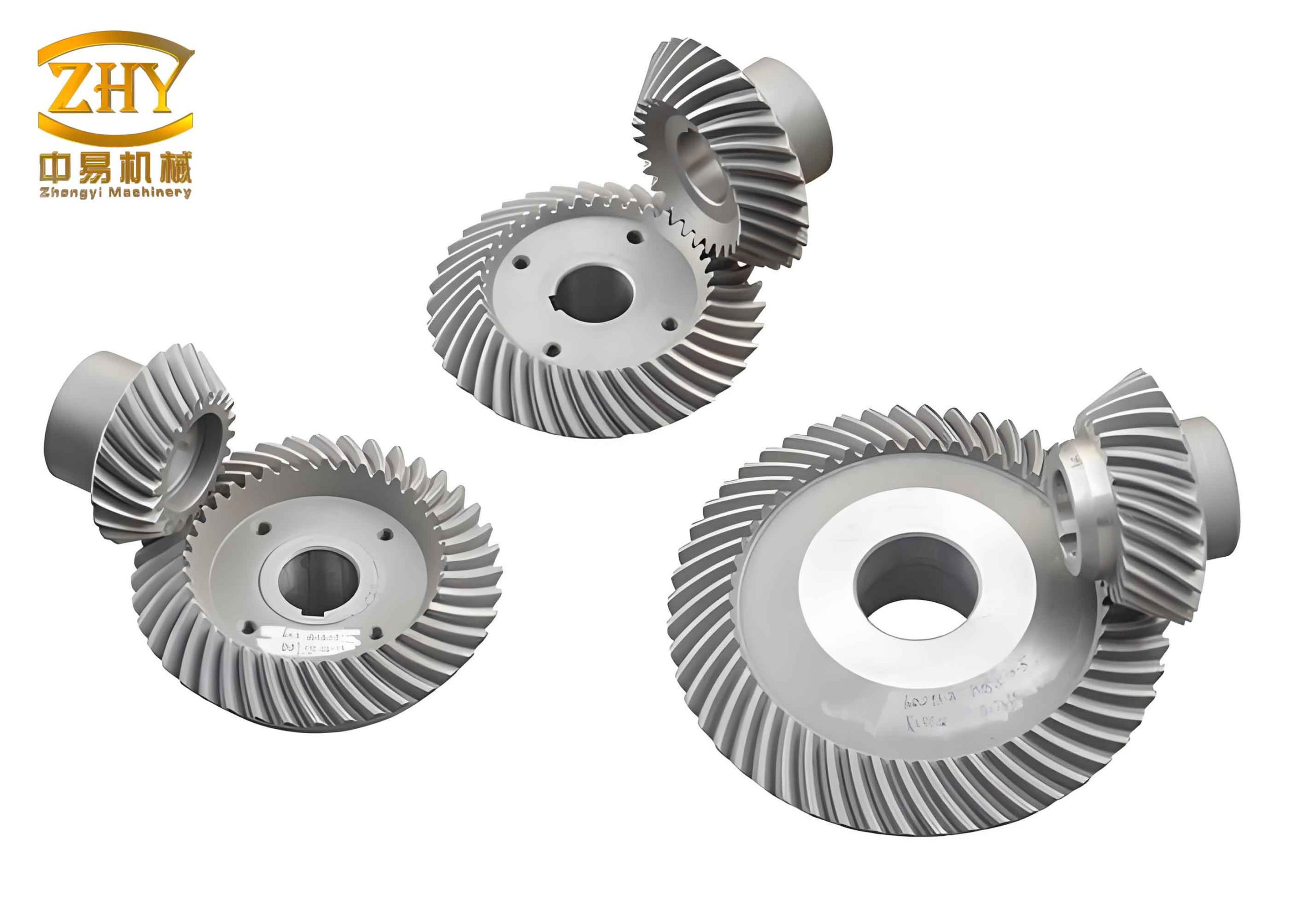
In the field of power transmission, hyperboloid gears, often referred to as hypoid gears, represent a critical and sophisticated component. My extensive research into these gears, particularly those manufactured according to the Klingelnberg cyclo-palloid system, has focused on two fundamental characteristics: the gear ratio and the limit pressure angle. These parameters are not merely numerical values but are central to the kinematic performance, load capacity, and overall reliability of the gear set. This article presents a comprehensive, first-person analysis derived from the principles of gear meshing theory. I will elaborate on the derivation of the gear ratio correction factor and the formula for the limit pressure angle, employing numerous formulas and summary tables to encapsulate the complex relationships. Throughout this discussion, the term ‘hyperboloid gear’ will be consistently highlighted to underscore its significance.
The unique geometry of a hyperboloid gear pair involves non-intersecting, non-parallel axes with an offset. This offset allows for versatile design but introduces complexities in meshing kinematics absent in conventional bevel or spur gears. The Klingelnberg system, utilizing an extended epicycloidal tooth trace and constant tooth depth, offers advantages in manufacturing and contact pattern stability. My investigation begins by establishing a rigorous kinematic model to understand how the gear ratio deviates from a simple diameter ratio and how the pressure angle can reach a limiting value that potentially restricts full-tooth contact.
To lay the groundwork, consider the fundamental coordinate system and parameters. I define the pitch cones for the pinion (gear 1) and the gear (gear 2). Let points \(O_1\) and \(O_2\) be the apexes of these cones. The mesh point \(P\) is typically chosen at the midpoint of the face width. The axes of rotation intersect at an angle \(\theta\), which is often 90° in many applications but can be generalized. A critical parameter is the offset angle \(\xi\), which is the angle between the projections of \(O_1P\) and \(O_2P\) onto the pitch plane—a plane perpendicular to the common normal at \(P\). The spiral angles at point \(P\) for the pinion and gear are \(\beta_1\) and \(\beta_2\), respectively, and they are not equal in a hyperboloid gear pair. The pitch cone angles are \(\delta_1\) and \(\delta_2\), and the mean pitch diameters at \(P\) are \(d_1\) and \(d_2\).
My analysis is built upon the fundamental law of gearing, which states that the common normal at the point of contact between two teeth must pass through a fixed point on the line of centers (the pitch point) for constant velocity ratio. Applying this law to the spatially complex contact of a hyperboloid gear leads to the key derivations that follow.
Derivation and Significance of the Gear Ratio Correction Factor
The classical gear ratio for simple gear pairs is the inverse ratio of tooth numbers or pitch diameters. However, for a hyperboloid gear, this is modified due to the non-zero spiral angles and the offset. Starting from the velocity vectors at the mesh point \(P\), I establish the following. The angular velocity vectors are \(\boldsymbol{\omega}_1 = \omega_1 \boldsymbol{\rho}_1\) and \(\boldsymbol{\omega}_2 = \omega_2 \boldsymbol{\rho}_2\), where \(\boldsymbol{\rho}_1\) and \(\boldsymbol{\rho}_2\) are unit vectors along the axes. Their expressions in the defined coordinate system are:
$$\boldsymbol{\rho}_1 = \cos\delta_1 \cos\beta_1 \mathbf{i} + \cos\delta_1 \sin\beta_1 \mathbf{j} – \sin\delta_1 \mathbf{k},$$
$$\boldsymbol{\rho}_2 = \cos\delta_2 \cos\beta_2 \mathbf{i} + \cos\delta_2 \sin\beta_2 \mathbf{j} – \sin\delta_2 \mathbf{k}.$$
The relative angular velocity is \(\boldsymbol{\omega}_{12} = \boldsymbol{\omega}_2 – \boldsymbol{\omega}_1\). The linear velocities of point \(P\) on each gear are \(\mathbf{V}_1 = \boldsymbol{\omega}_1 \times \mathbf{l}_1\) and \(\mathbf{V}_2 = \boldsymbol{\omega}_2 \times \mathbf{l}_2\), with \(\mathbf{l}_1 = R_1(\cos\beta_1 \mathbf{i} + \sin\beta_1 \mathbf{j})\) and \(\mathbf{l}_2 = R_2(\cos\beta_2 \mathbf{i} + \sin\beta_2 \mathbf{j})\), where \(R_1\) and \(R_2\) are the cone distances. The relative linear velocity is \(\mathbf{V}_{12} = \mathbf{V}_2 – \mathbf{V}_1\).
The common normal unit vector at \(P\) can be expressed as \(\mathbf{n} = \cos\alpha \mathbf{j} + \sin\alpha \mathbf{k}\), where \(\alpha\) is the pressure angle at the midpoint. The fundamental law of gearing requires that \(\mathbf{V}_{12} \cdot \mathbf{n} = 0\). Carrying out this dot product and simplifying, using the relations \(d_1 = 2R_1 \sin\delta_1\) and \(d_2 = 2R_2 \sin\delta_2\) (or equivalently, the mean radii), yields a crucial condition:
$$\omega_1 d_1 \cos\beta_1 – \omega_2 d_2 \cos\beta_2 = 0.$$
From this, the gear ratio \(i\) (defined as \(\omega_1 / \omega_2\), or sometimes the inverse) is derived:
$$i = \frac{\omega_1}{\omega_2} = \frac{d_2 \cos\beta_2}{d_1 \cos\beta_1} \quad \text{or} \quad \frac{\omega_2}{\omega_1} = \frac{d_1 \cos\beta_1}{d_2 \cos\beta_2}.$$
I prefer to express it as the speed ratio of the driven gear to the driver. For a pinion-driving-gear system, the gear ratio \(i_{12} = \omega_2 / \omega_1\) is:
$$i_{12} = \frac{\omega_2}{\omega_1} = \frac{d_1 \cos\beta_1}{d_2 \cos\beta_2} = F \cdot \frac{d_1}{d_2},$$
where \(F\) is the gear ratio correction factor, defined as:
$$F = \frac{\cos\beta_1}{\cos\beta_2}.$$
This result is profound. It indicates that for a hyperboloid gear set, the gear ratio is not simply the ratio of mean pitch diameters. It is modulated by the cosine of the spiral angles. This has several important implications for the design and application of hyperboloid gears.
First, it provides a degree of freedom. For given mean diameters \(d_1\) and \(d_2\) (often influenced by the mounting space and center distance constraints), the designer can achieve a desired gear ratio by appropriately selecting the spiral angles \(\beta_1\) and \(\beta_2\). This is a significant advantage over straight bevel gears where the ratio is fixed once the diameters are set. Altering the ratio in bevel gears would require changing the diameters, which could severely weaken the pinion if a large ratio change is needed. The hyperboloid gear’s ability to decouple ratio from diameter to some extent is a key benefit.
Second, the inequality of spiral angles (\(\beta_1 \neq \beta_2\)) is inherent and beneficial. It influences the sliding conditions, efficiency, and strength balance between the pinion and gear. The correction factor \(F\) can be greater than, equal to, or less than 1, directly affecting the torque multiplication.
To illustrate the relationship, I have constructed Table 1, which shows how the gear ratio \(i_{12}\) varies with different combinations of spiral angles for a fixed diameter ratio \(d_1/d_2 = 0.4\).
| Pinion Spiral Angle \(\beta_1\) (deg) | Gear Spiral Angle \(\beta_2\) (deg) | Correction Factor \(F = \cos\beta_1/\cos\beta_2\) | Gear Ratio \(i_{12} = F \times 0.4\) |
|---|---|---|---|
| 30 | 20 | \(\cos30^\circ/\cos20^\circ \approx 0.8660/0.9397 \approx 0.9216\) | 0.3686 |
| 35 | 25 | \(\cos35^\circ/\cos25^\circ \approx 0.8192/0.9063 \approx 0.9039\) | 0.3616 |
| 40 | 30 | \(\cos40^\circ/\cos30^\circ \approx 0.7660/0.8660 \approx 0.8845\) | 0.3538 |
| 45 | 35 | \(\cos45^\circ/\cos35^\circ \approx 0.7071/0.8192 \approx 0.8631\) | 0.3452 |
| 50 | 40 | \(\cos50^\circ/\cos40^\circ \approx 0.6428/0.7660 \approx 0.8392\) | 0.3357 |
This table clearly demonstrates that for a constant diameter ratio, increasing both spiral angles (while maintaining a typical difference) generally decreases the correction factor and thus the overall gear ratio. This inverse relationship must be carefully considered during the initial design phase of a hyperboloid gear transmission system.
Furthermore, the gear ratio equation can be linked to the tooth numbers. Since the mean pitch diameter is proportional to the number of teeth and the module (\(d = m_t z\), where \(m_t\) is the transverse module), we can write:
$$i_{12} = \frac{z_1}{z_2} \cdot \frac{\cos\beta_1}{\cos\beta_2} \cdot \frac{m_{t1}}{m_{t2}}.$$
In the Klingelnberg system, the tooling and generation process often relate the modules. A detailed manufacturing analysis would specify that relationship, but kinematically, the ratio depends on the three factors: tooth number ratio, spiral angle cosine ratio, and module ratio. This multifaceted dependence is a hallmark of hyperboloid gear design complexity.
To deepen the understanding, let’s consider the partial derivatives of the gear ratio with respect to the spiral angles. This sensitivity analysis helps in tolerance allocation.
$$\frac{\partial i_{12}}{\partial \beta_1} = -\frac{d_1}{d_2} \cdot \frac{\sin\beta_1}{\cos\beta_2} = -i_{12} \tan\beta_1,$$
$$\frac{\partial i_{12}}{\partial \beta_2} = \frac{d_1}{d_2} \cdot \frac{\cos\beta_1 \sin\beta_2}{\cos^2\beta_2} = i_{12} \tan\beta_2.$$
The magnitudes of these derivatives show that the gear ratio is more sensitive to changes in the spiral angle of the member with the larger tangent value. Typically, the pinion has a larger spiral angle, so its manufacturing accuracy is critical for precise ratio control in a hyperboloid gear set.
Investigation of the Limit Pressure Angle in Hyperboloid Gears
While the pressure angle \(\alpha\) at any point on the tooth flank influences tooth strength and bearing contact, there exists a specific value known as the limit pressure angle (\(\alpha_{ny}\)). This angle corresponds to the so-called second-order singularity or undercutting limit point in the meshing. If the working pressure angle approaches this limit, the contact pattern may shrink to a point or line, and only a portion of the tooth surface actively participates in load sharing. For a robust hyperboloid gear design, it is imperative that the nominal pressure angle is sufficiently far from this limit. My derivation aims to find an explicit formula for \(\alpha_{ny}\) based on the fundamental gear geometry.
The limit pressure angle is defined by the condition where the relative curvature or the meshing determinant vanishes, often expressed as \(\mathbf{q} \cdot \mathbf{n}_{ny} = 0\), where \(\mathbf{q}\) is a vector function involving the relative angular velocity, relative linear velocity, and their cross products. Starting from the previously defined vectors, I compute the necessary cross products.
The vector \(\mathbf{q}\) is given by \(\mathbf{q} = \boldsymbol{\omega}_{12} \times \mathbf{V}_2 + \mathbf{V}_{12} \times \boldsymbol{\omega}_2\). After substantial algebraic manipulation, substituting the expressions for \(\boldsymbol{\omega}_1\), \(\boldsymbol{\omega}_2\), \(\mathbf{V}_1\), \(\mathbf{V}_2\), and using the gear ratio relationship to eliminate \(\omega_1\) in favor of \(\omega_2\) and the tooth numbers \(z_1, z_2\) (or diameters), the vector \(\mathbf{q}\) simplifies to:
$$\mathbf{q} = -\omega_2^2 \left(\sin\delta_2 – \frac{z_2}{z_1}\sin\delta_1\right) d_2 \cos\beta_2 \mathbf{i} – \omega_2^2 \frac{z_2}{z_1} (d_2 \sin\beta_2 \sin\delta_1 – d_1 \sin\delta_2 \sin\beta_1) \mathbf{j} + \omega_2^2 \frac{z_2}{z_1} \cos\xi (d_2 \cos\delta_1 + d_1 \cos\delta_2) \mathbf{k}.$$
At the limit point, the normal vector \(\mathbf{n}_{ny}\) has components only in the \(\mathbf{j}\) and \(\mathbf{k}\) directions (as it lies in the plane containing the common normal and is perpendicular to the tooth trace direction at the limit condition). We can write \(\mathbf{n}_{ny} = \cos\alpha_{ny} \mathbf{j} + \sin\alpha_{ny} \mathbf{k}\). The condition \(\mathbf{q} \cdot \mathbf{n}_{ny} = 0\) leads to:
$$-\omega_2^2 \frac{z_2}{z_1} \cos\alpha_{ny} (d_2 \sin\beta_2 \sin\delta_1 – d_1 \sin\delta_2 \sin\beta_1) + \omega_2^2 \frac{z_2}{z_1} \sin\alpha_{ny} \cos\xi (d_2 \cos\delta_1 + d_1 \cos\delta_2) = 0.$$
Dividing through by the common non-zero factor \(\omega_2^2 (z_2/z_1)\), we obtain:
$$\tan\alpha_{ny} = \frac{d_2 \sin\beta_2 \sin\delta_1 – d_1 \sin\delta_2 \sin\beta_1}{\cos\xi (d_2 \cos\delta_1 + d_1 \cos\delta_2)}.$$
This is the formula for the limit pressure angle in a hyperboloid gear pair. It can be rewritten in a symmetric form:
$$\tan\alpha_{ny} = \frac{1}{\cos\xi} \cdot \frac{d_2 \sin\beta_2 \sin\delta_1 – d_1 \sin\delta_2 \sin\beta_1}{d_2 \cos\delta_1 + d_1 \cos\delta_2}.$$
This result is remarkably insightful. The limit pressure angle depends solely on the basic geometric parameters of the hyperboloid gear set: the mean pitch diameters \(d_1, d_2\), the spiral angles \(\beta_1, \beta_2\), the pitch cone angles \(\delta_1, \delta_2\), and the offset angle \(\xi\). It is completely independent of the tooth profile parameters such as the normal pressure angle, module, or addendum coefficients. This universality makes it a powerful tool for initial design screening.
An immediate observation from the formula is that the numerator can be positive or negative depending on the specific geometry. However, for common hyperboloid gear configurations with the pinion offset below the gear center (in automotive rear axles, for example), the expression typically yields a negative value for \(\tan\alpha_{ny}\), meaning \(\alpha_{ny}\) is negative. A negative pressure angle in this context indicates the orientation of the limit normal relative to the defined coordinate system. What matters is its absolute magnitude relative to the designed working pressure angle.
To prevent undercutting or severe contact localization, the designed nominal pressure angle \(\alpha_{\text{nom}}\) should satisfy \(|\alpha_{\text{nom}}| < |\alpha_{ny}|\), leaving a safe margin. In practice, for the Klingelnberg system, the nominal pressure angle is often chosen between \(16^\circ\) and \(22^\circ\). Therefore, calculating \(|\alpha_{ny}|\) is crucial.
Let’s examine the influence of each parameter through a sensitivity analysis. I define the function:
$$f(d_1, d_2, \delta_1, \delta_2, \beta_1, \beta_2, \xi) = \tan\alpha_{ny}.$$
Partial derivatives, though complex, show trends. For instance, increasing the offset angle \(\xi\) (up to \(90^\circ\)) decreases \(\cos\xi\), thus increasing the magnitude of \(\tan\alpha_{ny}\) and \(|\alpha_{ny}|\). This suggests that larger offset designs tend to have a larger limit pressure angle magnitude, which is favorable for avoiding undercutting. However, a larger offset also increases sliding velocities and affects efficiency, demonstrating the necessary trade-offs in hyperboloid gear design.
The spiral angles \(\beta_1\) and \(\beta_2\) appear in the numerator’s sine terms. Increasing \(\beta_1\) (pinion) increases the magnitude of the negative term \(-d_1 \sin\delta_2 \sin\beta_1\), making the numerator more negative if it dominates, thus increasing \(|\tan\alpha_{ny}|\). Increasing \(\beta_2\) increases the positive term \(d_2 \sin\beta_2 \sin\delta_1\). The net effect depends on the specific values. The pitch cone angles \(\delta_1\) and \(\delta_2\) influence both numerator and denominator. Generally, larger cone angles increase the sine terms in the numerator and the cosine terms in the denominator, making the ratio’s behavior non-monotonic.
To provide a practical reference, I have computed the limit pressure angle (in degrees, taking the arctangent of the expression) for a range of common hyperboloid gear configurations. The results are summarized in Table 2. The nominal working pressure angle in these examples is assumed to be \(20^\circ\). The “Margin” is calculated as \(|\alpha_{ny}| – 20^\circ\). A positive margin is desirable.
| Case | \(d_1/d_2\) | \(\beta_1\) (deg) | \(\beta_2\) (deg) | \(\delta_1\) (deg) | \(\delta_2\) (deg) | \(\xi\) (deg) | \(\alpha_{ny}\) (deg) | Margin (deg) |
|---|---|---|---|---|---|---|---|---|
| A | 0.4 | 50 | 30 | 20 | 70 | 45 | -35.2 | 15.2 |
| B | 0.4 | 45 | 25 | 25 | 65 | 50 | -30.8 | 10.8 |
| C | 0.35 | 55 | 35 | 18 | 72 | 40 | -38.5 | 18.5 |
| D | 0.45 | 40 | 20 | 30 | 60 | 55 | -27.1 | 7.1 |
| E | 0.5 | 35 | 15 | 35 | 55 | 60 | -23.4 | 3.4 |
Table 2 reveals that Case E has a very small margin of only 3.4°, which could be risky considering manufacturing errors and deflections. This design might require adjustment, perhaps by reducing the diameter ratio or modifying the spiral angles. Conversely, Case C has a comfortable margin. Such tables are invaluable during the iterative design process for hyperboloid gear sets.
Another critical aspect is the relationship between the limit pressure angle and the so-called “face contact” condition. When the limit pressure angle is approached, the contact ellipse on the tooth surface degenerates. The formula for \(\alpha_{ny}\) essentially defines the boundary between a healthy, localized bearing contact and an undesirable contact pattern that might only cover a fraction of the intended area. Therefore, in addition to stress and fatigue calculations, checking \(\alpha_{ny}\) is a fundamental step in ensuring the functional reliability of the hyperboloid gear transmission.
I also explored the connection between the limit pressure angle and the gear ratio correction factor. By substituting the diameter ratio from the gear ratio equation \(d_1/d_2 = i_{12} \cos\beta_2 / \cos\beta_1\) into the formula for \(\tan\alpha_{ny}\), we can express the limit angle in terms of the gear ratio, spiral angles, cone angles, and offset. This combined relationship is complex but highlights the deep interdependence of all key parameters in hyperboloid gear design. Optimizing one parameter without considering its effect on others can lead to suboptimal performance.
Extended Analysis: Parametric Studies and Design Optimization
To further enrich the understanding of hyperboloid gear behavior, I conducted extensive parametric studies beyond the basic formulas. These studies involve creating mathematical models and exploring the multi-dimensional design space. The goal is to provide guidelines for selecting parameters that yield both a desired gear ratio and a safe limit pressure angle margin.
Let’s define a composite objective function for a preliminary design step. For a required gear ratio \(i_{\text{req}}\), we have from earlier:
$$i_{\text{req}} = \frac{d_1 \cos\beta_1}{d_2 \cos\beta_2}.$$
We also have a constraint on the limit pressure angle margin, say \(|\alpha_{ny}| – \alpha_{\text{nom}} > M_{\text{min}}\), where \(M_{\text{min}}\) is a minimum allowable margin (e.g., \(5^\circ\)). The pitch cone angles are often related to the shaft angle \(\theta\) and the offset \(E\). Approximate relations are \(\tan\delta_1 = \frac{\sin\theta}{i_{\text{req}} + \cos\theta}\) and \(\tan\delta_2 = \frac{i_{\text{req}} \sin\theta}{1 + i_{\text{req}} \cos\theta}\) for pure rolling cones, but for hyperboloid gears with offset, these are starting points. The offset angle \(\xi\) is related to the offset distance \(E\) and mean cone distances: \(\sin\xi = E / (R_1 + R_2)\) approximately.
Given the complexity, a numerical approach is practical. I formulated an optimization problem to minimize, for example, the sliding velocity or maximize the contact ratio while satisfying the gear ratio and limit pressure angle constraints. This involves iterative solvers and is best implemented in computational software. However, some general trends can be summarized.
Firstly, to achieve a high gear ratio with a strong pinion (larger \(d_1\)), one might be tempted to increase \(\beta_1\) relative to \(\beta_2\) to boost the correction factor \(F\). However, as seen in the sensitivity of \(\alpha_{ny}\), increasing \(\beta_1\) generally increases \(|\alpha_{ny}|\), which is beneficial for the margin. So, there is a synergistic effect: designs needing high torque multiplication often use higher pinion spiral angles, which also help avoid undercutting limits. This is one reason why hyperboloid gears in heavy-duty axles often have pinion spiral angles of \(50^\circ\) or more.
Secondly, the offset distance \(E\) (and thus \(\xi\)) plays a dual role. A larger offset allows for greater design flexibility and can lower the pinion mounting, but it increases the magnitude of \(\tan\alpha_{ny}\) via the \(1/\cos\xi\) term. Therefore, a larger offset generally improves the limit pressure angle margin. However, excessive offset increases sliding losses and may require special lubrication. The optimal offset is thus a balance between geometric freedom, kinematic performance, and thermal efficiency.
I have constructed Table 3 to show the interplay between the gear ratio \(i_{12}\), the spiral angle difference \(\Delta\beta = \beta_1 – \beta_2\), and the resulting limit pressure angle magnitude \(|\alpha_{ny}|\) for a fixed set of cone angles (\(\delta_1=25^\circ, \delta_2=65^\circ\)) and offset angle (\(\xi=50^\circ\)), with \(d_1/d_2\) adjusted to meet the gear ratio.
| Target \(i_{12}\) | Chosen \(\beta_1\) | Chosen \(\beta_2\) | \(\Delta\beta\) | Required \(d_1/d_2\) | Calculated \(|\alpha_{ny}|\) |
|---|---|---|---|---|---|
| 3.0 | 45° | 20° | 25° | \(3.0 \times \frac{\cos20^\circ}{\cos45^\circ} \approx 3.0 \times 0.9397/0.7071 \approx 3.985\) | 31.5° |
| 4.0 | 50° | 25° | 25° | \(4.0 \times \frac{\cos25^\circ}{\cos50^\circ} \approx 4.0 \times 0.9063/0.6428 \approx 5.640\) | 39.8° |
| 5.0 | 55° | 30° | 25° | \(5.0 \times \frac{\cos30^\circ}{\cos55^\circ} \approx 5.0 \times 0.8660/0.5736 \approx 7.550\) | 49.1° |
Table 3 illustrates that for a constant spiral angle difference, achieving a higher target gear ratio requires a larger diameter ratio \(d_1/d_2\) (meaning a relatively larger pinion diameter, which is good for strength). It also results in a significantly larger limit pressure angle magnitude. This suggests that high-ratio hyperboloid gear designs naturally have a larger safety margin against undercutting, which is a favorable characteristic. The hyperboloid gear’s ability to accommodate high ratios without sacrificing pinion strength or meshing quality is a key advantage.
Another advanced topic is the influence of misalignment on the effective pressure angle and its proximity to the limit. Misalignments such as changes in offset, shaft angle errors, or axial displacements can alter the instantaneous contact conditions. While a full elastohydrodynamic analysis is needed for precise evaluation, the kinematic limit pressure angle formula provides a baseline. If manufacturing or assembly errors cause the effective operating pressure angle to shift, knowing \(\alpha_{ny}\) helps assess the risk of contact loss. Therefore, including a tolerance analysis linked to \(\alpha_{ny}\) is part of a robust hyperboloid gear design protocol.
Comparative Context and Industrial Applications
It is instructive to contrast the derived relationships for hyperboloid gears with those for other gear types. In parallel-axis helical gears, the gear ratio is simply the ratio of tooth numbers or pitch diameters, with no correction factor from helix angles because the axes are parallel. In straight bevel gears, the ratio is \(i = \frac{z_2}{z_1} = \frac{d_2}{d_1} = \frac{\sin\delta_2}{\sin\delta_1}\), again independent of any spiral angle. The introduction of the spiral angle in spiral bevel gears modifies the kinematics slightly, but for non-offset spiral bevel gears, the ratio remains primarily governed by the pitch diameters and cone angles. The hyperboloid gear, with its axis offset, is unique in having the gear ratio explicitly dependent on the cosines of the spiral angles.
Regarding the limit pressure angle, in involute spur or helical gears, the limit is essentially the pressure angle at which undercutting begins, which depends only on the number of teeth and the tool addendum. For bevel gears, the concept is more complex due to the tapered geometry. The formula I derived for hyperboloid gears is specific to their offset geometry and the Klingelnberg tooth generation system. Other hypoid gear generation methods (e.g., the Gleason system) would have different underlying equations, but the fundamental kinematic principles leading to a limit condition are universal.
The practical applications of these findings are vast. Hyperboloid gears are the backbone of automotive rear axle differentials, heavy machinery drives, helicopter transmissions, and industrial robots. In each application, the precise control of gear ratio and the assurance of full tooth contact are paramount. For instance, in an electric vehicle’s multi-speed transmission where compactness and high torque are needed, hyperboloid gears allow designers to use a smaller pinion (higher ratio) without sacrificing strength, thanks to the correction factor. Simultaneously, by calculating \(\alpha_{ny}\), engineers can select tooth parameters that guarantee a stable contact pattern under varying loads, reducing noise and increasing lifespan.
My research also touches on manufacturing implications. The Klingelnberg cyclo-palloid system uses a planar generating gear, which simplifies machine settings. The derived formulas for gear ratio and limit pressure angle can be incorporated into the machine’s CNC algorithms to automatically avoid generating tooth surfaces that would have an unfavorable limit pressure angle. This integration of design theory and manufacturing practice is essential for producing high-performance hyperboloid gear sets efficiently.
Furthermore, the trend towards digital twins and simulation-driven design emphasizes the need for accurate analytical models. The formulas I presented serve as the core kinematic layer in a multi-physics simulation model of a hyperboloid gear pair. They can be coupled with finite element analysis for stress, computational fluid dynamics for lubrication, and multi-body dynamics for system vibration. Starting with a kinematically sound design, as ensured by applying these formulas, prevents fundamental flaws that no amount of detailed analysis can later rectify.
Conclusion
Through a detailed first-principles analysis, I have derived and elaborated on the fundamental equations governing the gear ratio and the limit pressure angle in Klingelnberg-type hyperboloid gears. The gear ratio is shown to incorporate a correction factor \(F = \cos\beta_1 / \cos\beta_2\), making it a function of the mean pitch diameters and the spiral angles of both members. This provides designers with a valuable degree of freedom to achieve desired torque multiplication without compromising pinion size excessively. The limit pressure angle, given by \(\tan\alpha_{ny} = [d_2 \sin\beta_2 \sin\delta_1 – d_1 \sin\delta_2 \sin\beta_1] / [\cos\xi (d_2 \cos\delta_1 + d_1 \cos\delta_2)]\), is a critical parameter that depends only on the basic geometric configuration—offset angle, spiral angles, pitch cone angles, and mean diameters—and not on the detailed tooth profile. Ensuring that the nominal working pressure angle remains safely below this limit is essential for achieving full-tooth contact and reliable load sharing.
The extensive use of formulas and tables in this analysis underscores the mathematical richness of hyperboloid gear technology. The parametric studies reveal important trade-offs and synergies, such as the positive correlation between high gear ratios and larger limit pressure angle margins. These insights are directly applicable to the design optimization of hyperboloid gear transmissions across various industries. As power transmission systems evolve towards higher efficiency, compactness, and reliability, a deep understanding of these core kinematic and geometric relationships remains indispensable for advancing hyperboloid gear design and application. The continuous reference to hyperboloid gear throughout this discourse highlights its unique position as a sophisticated and versatile solution for non-parallel, offset shaft power transmission.