
In the realm of precision manufacturing, gear shaping stands as a critical process for producing internal gears, splines, and other complex tooth forms. As an engineer specializing in gear machining, I have extensively explored the nuances of gear shaping, particularly in the context of modifying standard gear shaping cutters for non-standard applications. This article delves into the fundamental principles, computational methodologies, and practical implementations of gear shaping, with a focus on adapting standard cutters for machining involute spline holes. Gear shaping is not merely a machining operation; it is a sophisticated interplay of kinematics, material science, and tool design. Through this discussion, I aim to provide a comprehensive guide that underscores the versatility and importance of gear shaping in modern industry.
Gear shaping involves the use of a cutter that reciprocates radially while rotating in sync with the workpiece to generate tooth profiles. This process is especially valuable for small-batch production, prototyping, and machining blind holes where other methods like broaching are impractical. The core challenge lies in ensuring that the cutter accurately produces the desired tooth geometry, which often requires modifications to standard tools. In my experience, the modification of standard gear shaping cutters for involute spline machining has proven to be a cost-effective and efficient solution. The following sections will elaborate on the underlying theory, design calculations, and validation techniques, enriched with tables and formulas to summarize key concepts. Gear shaping, when properly executed, can achieve high precision and surface quality, making it indispensable in aerospace, automotive, and machinery sectors.
The modification of a standard gear shaping cutter is rooted in the principles of internal gear meshing. Since the cutter and the gear engage in a backlash-free and tip-clearance meshing motion, the design must adhere to the laws of internal gear pair kinematics. This involves calculating parameters such as pressure angles, center distances, and cutter dimensions to ensure proper tooth generation without interference. For instance, when machining an involute spline hole with parameters like module m = 5 mm, pressure angle α = 20°, and number of teeth Z₂ = 30, one must select an appropriate standard cutter and then derive its modified specifications. The process begins with choosing a cutter based on the workpiece geometry, followed by computational steps to determine the cutter’s tip diameter, back angle, and other critical attributes. Gear shaping efficiency hinges on these precise calculations, which I will illustrate through detailed examples.
To elucidate the design process, let’s consider a specific case: machining an involute spline hole with the aforementioned parameters and an addendum modification coefficient x = +0.5. The standard gear shaping cutter selected has a module m = 5 mm, number of teeth Z₀ = 20, and tip diameter d_f = 100 mm. The first step involves determining the maximum addendum modification coefficient of the cutter on its front face, denoted as x₀_max. This is derived from the measured base tangent length over k teeth. For k = 3, the measured length W is 38.72 mm, and the theoretical length W’ for x₀ = 0 is 38.302 mm. Using the formula:
$$ x_{0max} = \frac{W – W’}{2m \sin \alpha} $$
we compute x₀_max ≈ 0.1222 mm. This value is crucial for subsequent adjustments. The back angle of the cutter’s tip, α_e, is typically 6° for standard tools, but it may change after modification. Gear shaping accuracy depends heavily on these initial parameters, and they must be verified through rigorous checks.
Next, we calculate the actual addendum modification coefficient x₂ for the internal gear (spline hole). This involves the measurement over pins or balls for even-numbered teeth. Given the pitch diameter d₂ = 150 mm and pin diameter d_p = 8 mm, the mean measurement M₂ is 145.5955 mm (averaging 145.719 mm and 145.472 mm). The pressure angle at the pin contact point, α_M, is found from:
$$ \cos \alpha_M = \frac{d_2 \cos \alpha}{M_2 + d_p} $$
yielding α_M ≈ 23°24’31”. Then, x₂ is computed using the involution function:
$$ \text{inv} \alpha_M = \text{inv} \alpha – \frac{d_p}{d_2 \cos \alpha} + \frac{\pi}{2Z_2} + \frac{2 x_2 \tan \alpha}{Z_2} $$
Solving for x₂ gives approximately 0.5709. This value represents the gear’s addendum shift and is essential for meshing calculations with the cutter. Gear shaping requires such precise determinations to avoid tooth interference and ensure smooth operation.
With x₂ known, we proceed to find the meshing angles between the cutter and the internal gear at critical points A and B on the cutter’s profile. Point A corresponds to the front face with x₀_max, and point B corresponds to the theoretical reference plane with x₀ = 0. The meshing angle α₀₂ is derived from the non-backlash meshing equation for internal gears:
$$ \text{inv} \alpha_{02} = \frac{2(x_2 – x_0) \tan \alpha}{Z_2 – Z_0} + \text{inv} \alpha $$
For point A: inv α₀₂_A ≈ 0.047567088, so α₀₂_A ≈ 28°53’17”. For point B: inv α₀₂_B ≈ 0.056462521, so α₀₂_B ≈ 30°27’27”. These angles influence the center distance a₀₂ between the cutter and gear, calculated as:
$$ a_{02} = \frac{m(Z_2 – Z_0)}{2} \cdot \frac{\cos \alpha}{\cos \alpha_{02}} $$
Thus, a₀₂_A ≈ 26.831 mm and a₀₂_B ≈ 27.253 mm. The tip diameters of the cutter at points A and B, d_aoA and d_aoB, are then determined from the gear’s root diameter D_f2 (mean value 165.135 mm):
$$ d_{ao} = D_{f2} – 2a_{02} $$
giving d_aoA ≈ 111.473 mm and d_aoB ≈ 110.629 mm. The distance b between the reference plane and the front face is related to x₀_max by:
$$ b = \frac{x_{0max} m}{\tan \alpha_e} $$
with α_e = 6°, so b ≈ 5.85 mm. However, after modification, the back angle α_e’ may differ. It is computed from the tip diameter variation:
$$ \alpha_e’ = \arctan \left( \frac{(d_{aoA} – d_{aoB}) \times 0.5}{b} \right) $$
yielding α_e’ ≈ 4°10′. Therefore, the modified cutter parameters are: tip diameter 111.473 mm and tip back angle 4°10′. These values ensure that the gear shaping process generates the correct spline profile without undercutting or excessive wear.
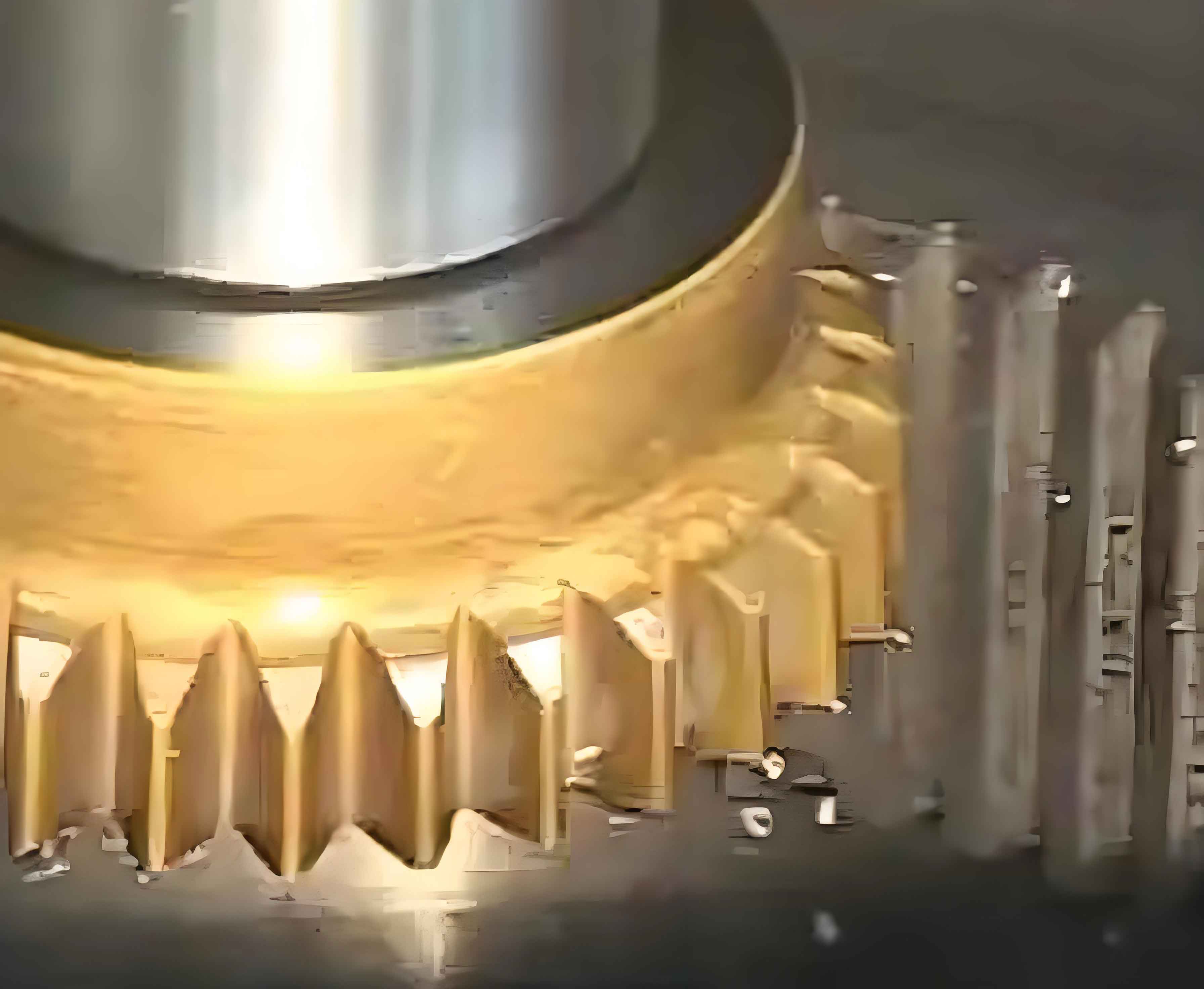
To validate the modification, we must check the cutter’s performance at negative addendum modification points, such as C and D, located at distances b and 2b from the reference plane. For point C, x₀_C = -0.1222 mm, and for point D, x₀_D = -0.2444 mm. Using α_e’ = 4°10′, the tip diameters at these points are:
$$ d_{aoC’} = d_{aoA} – 2(2b \tan \alpha_e’) $$
$$ d_{aoD’} = d_{aoA} – 2(3b \tan \alpha_e’) $$
giving d_aoC’ ≈ 109.783 mm and d_aoD’ ≈ 108.938 mm. The meshing angles and center distances are recalculated: α₀₂_C ≈ 31°51’05”, a₀₂_C ≈ 27.657 mm; α₀₂_D ≈ 33°06’32”, a₀₂_D ≈ 28.046 mm. The resulting root diameters of the internal gear are D_fC ≈ 165.097 mm and D_fD ≈ 165.030 mm, which should comply with design tolerances (e.g., 165.185–165.085 mm). Slight adjustments may be needed to avoid exceeding limits, but overall, the modification proves effective. This iterative verification is a hallmark of reliable gear shaping practices.
Beyond calculations, the practical aspects of gear shaping warrant attention. Tool wear, material selection, and cutting conditions significantly impact the process. For instance, coated gear shaping cutters can mitigate “tool polishing” phenomena common in heat-treated gears, enhancing lifespan and accuracy. The dynamics of gear shaping also involve vibrational considerations; improper parameters can lead to chatter, affecting surface finish. In my work, I have observed that optimizing reciprocation speed, feed rate, and coolant application can reduce such issues. Moreover, gear shaping is not limited to involute splines; it applies to cycloidal profiles, serrations, and custom shapes, showcasing its adaptability. The table below summarizes key parameters for gear shaping cutter modification based on common involute spline specifications.
| Parameter | Symbol | Formula or Value | Remarks |
|---|---|---|---|
| Module | m | 5 mm | Base unit for sizing |
| Pressure Angle | α | 20° | Standard for many gears |
| Number of Teeth (Gear) | Z₂ | 30 | Workpiece specification |
| Number of Teeth (Cutter) | Z₀ | 20 | Selected from standard |
| Cutter Tip Diameter (Initial) | d_f | 100 mm | Based on cutter catalog |
| Max Addendum Modification (Cutter) | x₀_max | 0.1222 mm | From base tangent measurement |
| Gear Addendum Modification | x₂ | 0.5709 | Computed via pin measurement |
| Meshing Angle at Point A | α₀₂_A | 28°53’17” | For modified cutter front face |
| Meshing Angle at Point B | α₀₂_B | 30°27’27” | For cutter reference plane |
| Center Distance at A | a₀₂_A | 26.831 mm | Critical for clearance |
| Center Distance at B | a₀₂_B | 27.253 mm | Ensures proper engagement |
| Modified Cutter Tip Diameter | d_aoA | 111.473 mm | Final machining dimension |
| Modified Tip Back Angle | α_e’ | 4°10′ | Reduced due to modification |
| Validation Root Diameter (Point C) | D_fC | 165.097 mm | Within tolerance |
| Validation Root Diameter (Point D) | D_fD | 165.030 mm | May need minor adjustment |
The mathematical foundation of gear shaping extends to stress analysis and fatigue considerations. During machining, the cutter undergoes cyclic loads that can lead to wear or breakage. The fatigue crack growth rate, as described by Paris’ law, is relevant for tool life prediction:
$$ \frac{da}{dN} = c(\Delta K)^m $$
where da/dN is the crack growth per cycle, ΔK is the stress intensity factor range, c is a material constant, and m is an exponent (often 3 for steel). For gear shaping cutters, ΔK must exceed a threshold (e.g., 6.6 MN/m³/² for steel) to initiate crack propagation. This underscores the importance of material toughness and defect-free manufacturing in gear shaping tools. In practice, I recommend using high-speed steel or carbide with adequate hardness and fatigue resistance. Additionally, geometric optimizations, such as varying rake angles or relief profiles, can distribute stresses more evenly, prolonging tool life. Gear shaping, therefore, integrates mechanical design with durability science.
Another aspect is the historical evolution of gear shaping. From mechanical shapers to CNC-controlled versions, the technology has advanced significantly. Modern gear shaping machines offer programmable motions, real-time monitoring, and adaptive control, enabling complex profiles like hypoid gears. The principles, however, remain rooted in the kinematics I have described. For example, the generation of an involute curve relies on the rolling action between cutter and workpiece, expressed mathematically as:
$$ x = r_b (\cos \theta + \theta \sin \theta) $$
$$ y = r_b (\sin \theta – \theta \cos \theta) $$
where r_b is the base radius and θ is the roll angle. This parametric equation guides the cutter path in gear shaping, ensuring accurate tooth forms. Computer-aided design (CAD) software now automates such calculations, but understanding the underlying theory is vital for troubleshooting. In my experience, manual computations, as shown earlier, foster deeper insights into gear shaping nuances.
The application of gear shaping in industry is vast. Beyond spline holes, it is used for internal gears in planetary gearboxes, pump rotors, and transmission components. The process is particularly advantageous for hard-to-machine materials like titanium or hardened steels, where broaching may be ineffective. With proper cutter modification, gear shaping can achieve tolerances within IT7-IT8 grades and surface roughness Ra < 1.6 µm. The table below compares gear shaping with other gear machining processes.
| Process | Accuracy | Productivity | Flexibility | Typical Applications |
|---|---|---|---|---|
| Gear Shaping | High | Moderate | High (adaptable to custom shapes) | Internal gears, splines, blind holes |
| Broaching | Very High | High for large batches | Low (dedicated tools) | Through holes, keyways |
| Hobbing | High | High | Moderate (external gears mainly) | External spur and helical gears |
| Milling | Moderate | Low to Moderate | High (CNC versatile) | Prototyping, complex profiles |
| Grinding | Very High | Low | Moderate | Hardened gears, precision finishing |
From this comparison, gear shaping excels in flexibility, making it ideal for small batches and complex geometries. However, it requires skilled setup and precise cutter preparation. The modification calculations I detailed are part of this preparation, ensuring that standard tools can be repurposed efficiently. This reduces costs and lead times, which is crucial in competitive manufacturing environments.
Looking forward, innovations in gear shaping include laser-assisted machining, additive manufacturing of cutters, and AI-driven optimization. For instance, laser surface texturing can enhance cutter lubrication, reducing wear. Similarly, simulation software can predict meshing errors before physical trials. As an engineer, I envision gear shaping becoming more integrated with digital twins, where virtual models validate modifications in real-time. The core principles, though, will remain anchored in the kinematic and geometric relationships I have expounded.
In conclusion, gear shaping is a multifaceted process that combines theoretical rigor with practical craftsmanship. Through cutter modification, standard tools can be adapted for specialized tasks like involute spline machining, demonstrating the adaptability of gear shaping. The calculations involving addendum modification, meshing angles, and diameter adjustments are essential for success. By incorporating fatigue analysis and historical context, we appreciate the broader implications of gear shaping in engineering. As technology advances, gear shaping will continue to evolve, but its foundation in precise computation and material science will endure. I hope this exposition provides valuable insights for practitioners and enthusiasts alike, reinforcing the significance of gear shaping in modern manufacturing.