1. Introduction
In the realm of mechanical engineering, transmission systems are the linchpins that ensure the efficient operation of various 机械设备. Among them, the new bevel gear-roller flat disk transmission stands out for its unique design and potential for high – performance applications. However, the complex and variable working environments pose significant challenges to maintaining a constant speed output. This has spurred researchers to explore advanced control strategies.
1.1 Significance of Transmission Systems
Transmission systems are crucial in converting rotational speed and torque, which is essential for different machinery functions. They are widely used in automotive, industrial equipment, and aerospace industries. A well – designed transmission system can enhance the overall efficiency of a machine, reduce energy consumption, and extend its service life. For example, in the automotive industry, a high – quality transmission system enables smooth gear shifting, improving fuel economy and driving comfort.
1.2 Challenges of the New Bevel Gear – Roller Flat Disk Transmission
The new bevel gear – roller flat disk transmission combines the advantages of bevel gear and roller flat disk mechanisms. The bevel gear part is responsible for changing the transmission ratio, while the roller flat disk part ensures smooth torque transfer. Nevertheless, its performance is affected by several factors. The nonlinear characteristics of the system, such as the complex relationship between load and transmission ratio, and the uncertainties introduced by friction and external disturbances, make it difficult to achieve stable and accurate constant – speed output through traditional control methods.
1.3 Research Motivation
The limitations of traditional control methods in dealing with the challenges of the new bevel gear – roller flat disk transmission have led to the search for more effective control strategies. Fuzzy PID control, which combines the flexibility of fuzzy logic and the precision of PID control, has shown great potential in handling complex and uncertain systems. By applying fuzzy PID control to this transmission, we aim to improve its constant – speed output performance, enhance system adaptability, and provide a more reliable solution for practical applications.
2. Overview of the New Bevel Gear – Roller Flat Disk Transmission
2.1 Structure and Working Principle
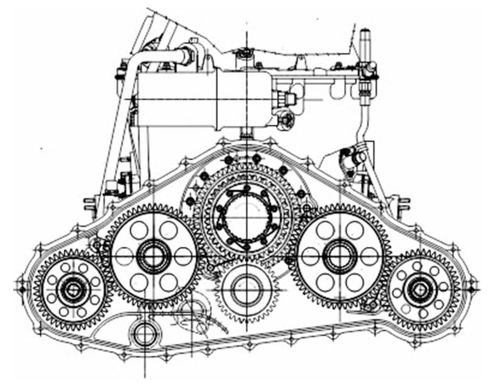
The new bevel gear – roller flat disk transmission consists of two main parts: the bevel gear unit and the roller flat disk unit. As shown in Figure 1, the bevel gear unit is composed of multiple bevel gears, which work together to adjust the transmission ratio. The roller flat disk unit includes rollers that roll on a flat disk, transmitting torque in the process.
| Component | Function |
|---|---|
| Bevel Gears | Change the transmission ratio |
| Rollers | Roll on the flat disk for torque transfer |
| Flat Disk | Provide a surface for roller rolling |
When the input shaft rotates, the bevel gears adjust the rotational speed and direction, and then the rollers on the flat disk transfer the power to the output shaft. The combination of these two parts allows for a wide range of speed and torque adjustments.
2.2 Key Performance Indicators
The key performance indicators of the new bevel gear – roller flat disk transmission include transmission efficiency, speed range, and torque capacity. In ideal conditions, its transmission efficiency can reach over 95%, which is quite high compared to some traditional transmissions. The speed range typically spans from 500r/min to 3000r/min, meeting the requirements of many applications, such as automotive and industrial machinery. The torque capacity depends on factors like the size of the gears, the material used, and the design of the roller – flat disk interface.
| Performance Indicator | Typical Value |
|---|---|
| Transmission Efficiency | >95% |
| Speed Range | 500 – 3000r/min |
| Torque Capacity | Varies based on design |
3. Fuzzy PID Control Theory
3.1 Basics of PID Control
PID control is a widely used control algorithm in industrial automation. It consists of three components: proportional (P), integral (I), and derivative (D). The proportional term adjusts the control output based on the current error between the setpoint and the measured value. The integral term accumulates the error over time to eliminate the steady – state error, and the derivative term predicts the future trend of the error based on its rate of change.
The general formula for PID control is: \(u(t)=K_{p}e(t)+K_{i}\int_{0}^{t}e(t)dt + K_{d}\frac{de(t)}{dt}\) where \(u(t)\) is the control output, \(K_{p}\) is the proportional coefficient, \(K_{i}\) is the integral coefficient, \(K_{d}\) is the derivative coefficient, and \(e(t)\) is the error between the setpoint and the measured value.
| Component | Function | Impact on System |
|---|---|---|
| Proportional (\(K_{p}\)) | Adjusts output based on current error | Increases response speed, but may cause overshoot if too large |
| Integral (\(K_{i}\)) | Eliminates steady – state error by accumulating error | Enhances steady – state performance, but may slow down the system or cause instability if too large |
| Derivative (\(K_{d}\)) | Predicts error trend based on error rate of change | Reduces overshoot and improves dynamic response, but may increase sensitivity to noise if too large |
3.2 Introduction to Fuzzy Logic
Fuzzy logic is a form of multi – valued logic that allows for more flexible and human – like decision – making in control systems. It deals with vague and uncertain information by using fuzzy sets and membership functions. In a fuzzy system, input variables are first fuzzified, which means they are mapped to fuzzy sets. Then, based on a set of predefined fuzzy rules, the system makes decisions. Finally, the output is defuzzified to obtain a precise control value.
For example, in the case of controlling the speed of the new bevel gear – roller flat disk transmission, the input variables such as speed error and error change rate can be fuzzified into linguistic terms like “negative large”, “negative small”, “zero”, “positive small”, and “positive large”. The fuzzy rules then determine how to adjust the PID parameters based on these linguistic terms.
3.3 Combining Fuzzy Logic with PID Control
Fuzzy PID control combines the advantages of both fuzzy logic and PID control. The fuzzy part is used to adjust the PID parameters (\(K_{p}\), \(K_{i}\), \(K_{d}\)) in real – time according to the system’s operating conditions. When the system is in a state of large error, the fuzzy logic can quickly adjust the PID parameters to make the system respond faster. As the error decreases, the fuzzy logic can fine – tune the parameters to ensure stable operation and high – precision control.
4. Fuzzy PID Control for the New Bevel Gear – Roller Flat Disk Transmission
4.1 Dynamic Modeling of the Transmission
To implement effective control, it is necessary to establish a dynamic model of the new bevel gear – roller flat disk transmission. The model takes into account the impact of load changes on the transmission ratio. Let the input shaft speed be \(\omega_{in}\), the output shaft speed be \(\omega_{out}\), and the load coefficient be \(k_{L}\). The transmission ratio i of the bevel gear part is given by: \(\left\{\begin{array}{l} \omega_{out }=\frac{\omega_{in }}{i} \\ i=\frac{N_{1}}{N_{2}} \cdot k_{L}\left(T_{out }\right) \end{array}\right.\) where \(N_{1}\) and \(N_{2}\) are the numbers of teeth of two bevel gears, and \(k_{L}(T_{out })\) is a nonlinear function of the output torque \(T_{out }\) representing the load effect on the transmission ratio.
For the roller flat disk part, the rolling resistance torque \(M_{r}\) is considered. Given the friction coefficient \(\mu\) between the roller and the flat disk, the normal pressure \(F_{n}\), and the rolling resistance coefficient \(f_{r}\), the rolling resistance torque \(M_{r}\) can be expressed as: \(M_{r}=f_{r}(v, \alpha, \mu, \rho, … .) \cdot F_{n} \cdot R\) where v is the roller linear velocity, \(\alpha\) is the roller angular acceleration, \(\rho\) is the material density, and R is the roller radius.
Combining the dynamics of the bevel gear and roller flat disk parts, the overall dynamic equation of the transmission is: \(T_{in } \cdot \frac{1}{i}-T_{out }=J_{out } \cdot \frac{d \omega_{out }}{d t}+M_{r}\) where \(J_{out }\) is the moment of inertia of the output shaft, and \(T_{in }\) and \(T_{out }\) are the input and output shaft torques respectively.
| Parameter | Meaning |
|---|---|
| \(\omega_{in}\) | Input shaft speed |
| \(\omega_{out}\) | Output shaft speed |
| i | Transmission ratio |
| \(k_{L}\) | Load coefficient |
| \(N_{1}\), \(N_{2}\) | Number of teeth of bevel gears |
| \(M_{r}\) | Rolling resistance torque |
| \(\mu\) | Friction coefficient |
| \(f_{r}\) | Rolling resistance coefficient |
| \(J_{out }\) | Moment of inertia of output shaft |
| \(T_{in }\), \(T_{out }\) | Input and output shaft torques |
4.2 Fuzzy Condition Setting
4.2.1 Input Variable Selection
The two main input variables for the fuzzy PID controller are the error e and the error change rate ec. The error e is the difference between the actual speed and the set – point speed, i.e., \(e = e_{1}-e_{2}\), where \(e_{1}\) is the measured value and \(e_{2}\) is the set value. The error change rate ec reflects the trend of the error change over time and is calculated as \(ec=\frac{e_{k}-e_{k – 1}}{\Delta t}\), where \(e_{k}\) is the current error, \(e_{k – 1}\) is the previous error, and \(\Delta t\) is the time interval.
4.2.2 Fuzzy Sets and Membership Functions
Fuzzy sets are defined for the error e and the error change rate ec. Common fuzzy sets include {Negative Big, Negative Medium, Negative Small, Zero, Positive Small, Positive Medium, Positive Big}, denoted as {NB, NM, NS, Z, PS, PM, PB}. Membership functions are used to describe the degree to which a value belongs to a particular fuzzy set. For example, a triangular membership function can be used to represent the fuzzy set “Positive Small”.
| Fuzzy Set | Linguistic Term |
|---|---|
| NB | Negative Big |
| NM | Negative Medium |
| NS | Negative Small |
| Z | Zero |
| PS | Positive Small |
| PM | Positive Medium |
| PB | Positive Big |
4.2.3 Fuzzy Rule Base
The fuzzy rule base is established based on expert experience and the dynamic characteristics of the system. The rules are in the form of “If e is X and ec is Y, then \(K_{p}\) is \(Z_{1}\), \(K_{i}\) is \(z_{2}\), \(K_{d}\) is \(Z_{3}\)”, where X, Y, \(Z_{1}\), \(z_{2}\), \(Z_{3}\) are elements of the fuzzy sets. For example, if the error e is “Positive Big” and the error change rate ec is “Positive Small”, the rule might increase \(K_{p}\) to quickly reduce the large error and adjust \(K_{i}\) and \(K_{d}\) to ensure stable control.
4.2.4 Fuzzy Inference and Defuzzification
Fuzzy inference is carried out using a fuzzy inference engine. Given the input values of e and ec, the engine determines the adjustments of the PID parameters (\(\Delta K_{p}\), \(\Delta K_{i}\), \(\Delta K_{d}\)) according to the fuzzy rules. Defuzzification is then used to convert the fuzzy output into a precise value. One common defuzzification method is the weighted average method.
4.3 Design of the Fuzzy PID Controller for Transmission Constant – Speed Output
The fuzzy PID controller for the new bevel gear – roller flat disk transmission takes the output shaft speed deviation and its change rate as inputs and outputs the parameter adjustments \(\Delta K_{p}\), \(\Delta K_{i}\), \(\Delta K_{d}\) of the PID controller.
First, the input variables are fuzzified. Suppose the basic domain of the system deviation is \([-E, E]\) and the fuzzy – fied discrete domain is \([-n, n]\), the quantization factor \(k_{e}\) is calculated as \(k_{e}=\frac{n}{E}\). Similarly, for the deviation change rate with a basic domain of \([-EC, EC]\) and a fuzzy – fied discrete domain of \([-m, m]\), the quantization factor \(k_{ec}\) is \(k_{ec}=\frac{m}{EC}\).
The adjusted PID parameters are calculated as: \(\left\{\begin{array}{l} K_{p}=K_{p1}+\Delta K_{p} \\ K_{i}=K_{i1}+\Delta K_{i} \\ K_{d}=K_{d1}+\Delta K_{d} \end{array}\right.\) where \(K_{p1}\), \(K_{i1}\), \(K_{d1}\) are the initial parameters of the system.
| Parameter | Function | Adjustment Principle |
|---|---|---|
| \(K_{p}\) | Proportional coefficient | Increases system response speed. Adjusted based on error and error change rate to balance response and stability |
| \(K_{i}\) | Integral coefficient | Eliminates steady – state error. Adjusted considering static error to avoid integral saturation |
| \(K_{d}\) | Derivative coefficient | Improves dynamic characteristics. Adjusted based on error change rate to predict and suppress deviation changes |
4.4 Output of Fuzzy PID Control Quantity
After the fuzzy PID control, the fuzzy rules are designed, and the defuzzification method is used to convert the fuzzy output into precise PID parameter adjustments. The adjusted PID parameters are then used to calculate the control quantity.
The fuzzy control rules for the transmission constant – speed deviation are established, dividing the deviation into {Negative Big, Negative Medium, Negative Small, Zero, Positive Small, Positive Medium, Positive Big}. The control quantity \(u(t)\) is calculated as: \(u(t)=K_{p}(t) \cdot e(t)+K_{i}(t) \int_{0}^{t}e(t)dt+K_{d}(t) \frac{d e(t)}{dt}\) where \(K_{p}(t)\), \(K_{i}(t)\), \(K_{d}(t)\) are the updated PID parameters, \(e(t)\) is the output shaft speed deviation, and \(u(t)\) is the control quantity. The control quantity \(u(t)\) is then converted into an adjustment instruction for the input shaft speed or torque and sent to the transmission actuator to achieve constant – speed control of the output shaft.
5. Simulation Experiments
5.1 Experimental Setup
To verify the superiority of the proposed fuzzy PID control method for the new bevel gear – roller flat disk transmission, a simulation experiment was conducted. Two conventional transmission constant – speed control methods, namely the MPC – based method and the ant – colony – algorithm – based method, were selected as comparison objects.
A simulation platform was built using MATLAB. The new bevel gear – roller flat disk transmission model was established, and its parameters were configured as shown in Table 1.
| Parameter | Configuration |
|---|---|
| Input bevel gear 1 teeth number \(z_{1}\) | 50 |
| Bevel gear 3/4 teeth number | 55 |
| Bevel gear 5/6 teeth number | 65 |
| Input bevel gear 2 teeth number \(z_{2}\) | 60 |
| Roller radius/mm | 50 |
| Flat disk radius/mm | 70 |
| Rolling resistance coefficient | 0.15 |
| Load coefficient \(k_{L}\) | 0.01 |
| Number of added neurons | 5 |
| Maximum number of neurons | 100 |
| PID proportional coefficient | 0.1 |
| Integral time constant | 0.0004 |
| Differential time constant | 5.95 |
Table 1: Transmission Simulation Model Modeling Parameters
5.2 Experimental Results and Analysis
The simulation results of the transmission speed output under different control methods are shown in Figure 2. In different load torque conditions (150N·m and 350N·m), the proposed fuzzy PID control method can achieve speed output control within a shorter adjustment time, with the adjustment time within 4s in both cases.
To further evaluate the control accuracy, the overshoot of different control methods was compared, as shown in Table 2. It can be clearly seen that the new bevel gear – roller flat disk transmission constant – speed output fuzzy PID control method has a significantly lower overshoot and higher control accuracy compared to the two conventional control methods.
| Load Torque (N·m) | Fuzzy PID Control Overshoot (%) | MPC – based Control Overshoot (%) | Ant – colony – algorithm – based Control Overshoot (%) |
|---|---|---|---|
| 150 | 3.10 | 4.53 | 5.54 |
| 350 | 3.36 | 4. |
5.3 Discussion of Experimental Results
The experimental results clearly demonstrate the effectiveness of the proposed fuzzy PID control strategy for the new bevel gear – roller flat disk transmission. The fuzzy PID controller can adaptively adjust the PID parameters based on the real – time error and error change rate, which enables it to handle the nonlinear and uncertain characteristics of the transmission system more effectively.
The ability to quickly respond to load changes is a significant advantage of the fuzzy PID control method. In practical applications, sudden changes in load are common, and a control system that can rapidly adjust to these changes is essential for maintaining stable operation. The fuzzy PID controller can quickly increase or decrease the control output to compensate for the load – induced speed variations, ensuring that the output speed remains close to the set – point.
Another important aspect is the reduction of overshoot. A large overshoot not only indicates poor control accuracy but also may cause additional wear and tear on the transmission components. The fuzzy PID control method can optimize the control process by adjusting the PID parameters in a more intelligent way, minimizing the overshoot and improving the overall performance and reliability of the transmission system.
6. Applications and Future Prospects
6.1 Potential Applications
The new bevel gear – roller flat disk transmission with fuzzy PID control has a wide range of potential applications. In the automotive industry, it can be used in modern vehicle transmissions to improve fuel efficiency and driving comfort. The ability to maintain a constant speed output under various driving conditions, such as acceleration, deceleration, and uphill/downhill driving, can enhance the vehicle’s performance and reduce emissions.
In industrial machinery, such as conveyor belts, machine tools, and robotic arms, this transmission – control system can ensure stable and accurate operation. For example, in a conveyor belt system, a constant – speed output is crucial for the proper transportation of materials. The fuzzy PID – controlled transmission can effectively deal with the fluctuations in load caused by different material weights and conveyor belt lengths, ensuring smooth operation.
In the aerospace field, where high – precision and reliable transmission systems are required, the new bevel gear – roller flat disk transmission with fuzzy PID control can also play an important role. It can be used in aircraft engines, landing gear systems, and satellite – borne equipment to provide stable power transmission and precise speed control.
6.2 Future Research Directions
Although the fuzzy PID control method shows excellent performance in this study, there is still room for further improvement. One direction is to explore more advanced fuzzy rule – generation techniques. Currently, the fuzzy rules are mainly established based on expert experience and simple system analysis. In the future, machine – learning algorithms can be integrated to automatically generate and optimize the fuzzy rules, making the control system more intelligent and adaptable.
Another area of research is to combine the fuzzy PID control with other advanced control strategies. For example, neural – network – based control methods can be integrated with fuzzy PID control. Neural networks have strong learning and approximation capabilities, which can help to better model the complex nonlinear relationship in the transmission system. By combining these two methods, a more powerful and comprehensive control system can be developed.
In addition, the influence of more complex factors on the transmission system, such as temperature variations, material fatigue, and manufacturing errors, should be considered in future research. These factors can have a significant impact on the performance of the transmission system over time, and a more comprehensive control strategy that takes these factors into account is needed to ensure long – term stable operation.
7. Conclusion
This paper has comprehensively explored the fuzzy PID control for the constant – speed output of the new bevel gear – roller flat disk transmission. Through in – depth analysis of the transmission structure, working principle, and control theory, a complete fuzzy PID control system has been designed.
The dynamic modeling of the transmission considered the impact of load changes and friction, providing a solid foundation for accurate control. The fuzzy PID controller, with its unique fuzzy condition setting and parameter – adjustment mechanism, effectively addressed the nonlinear and uncertain characteristics of the transmission system.
The simulation experiments, comparing with conventional control methods, clearly demonstrated the superiority of the proposed fuzzy PID control method in terms of control accuracy and response speed. It achieved lower overshoot and shorter adjustment time under different load torque conditions.
The new bevel gear – roller flat disk transmission with fuzzy PID control has broad application prospects in various fields. Future research can focus on further optimizing the control strategy, integrating more advanced techniques, and considering complex influencing factors to continuously improve the performance and reliability of the transmission system. Overall, this research provides a valuable reference for the development of high – performance transmission control systems.