This paper focuses on the fuzzy PID control method for the constant speed output of the new bevel gear – roller flat disk transmission. It elaborates on the modeling process of the transmission, the design of the fuzzy PID controller, and the experimental verification. The research results show that this control method can effectively improve the control accuracy and stability of the transmission, providing a new solution for the performance optimization of the transmission system.
1. Introduction
In modern mechanical engineering, the performance of the transmission system is crucial for the operation efficiency and service life of the equipment. The transmission, as a key device for realizing the conversion of different speeds and torques, has always been a research hotspot in this field. The new bevel gear – roller flat disk transmission has unique structural and transmission characteristics, but traditional control methods often cannot meet the requirements of constant speed output in complex working environments. Therefore, it is necessary to explore more advanced control strategies.
2. New Bevel Gear – Roller Flat Disk Transmission
2.1 Structure and Working Principle
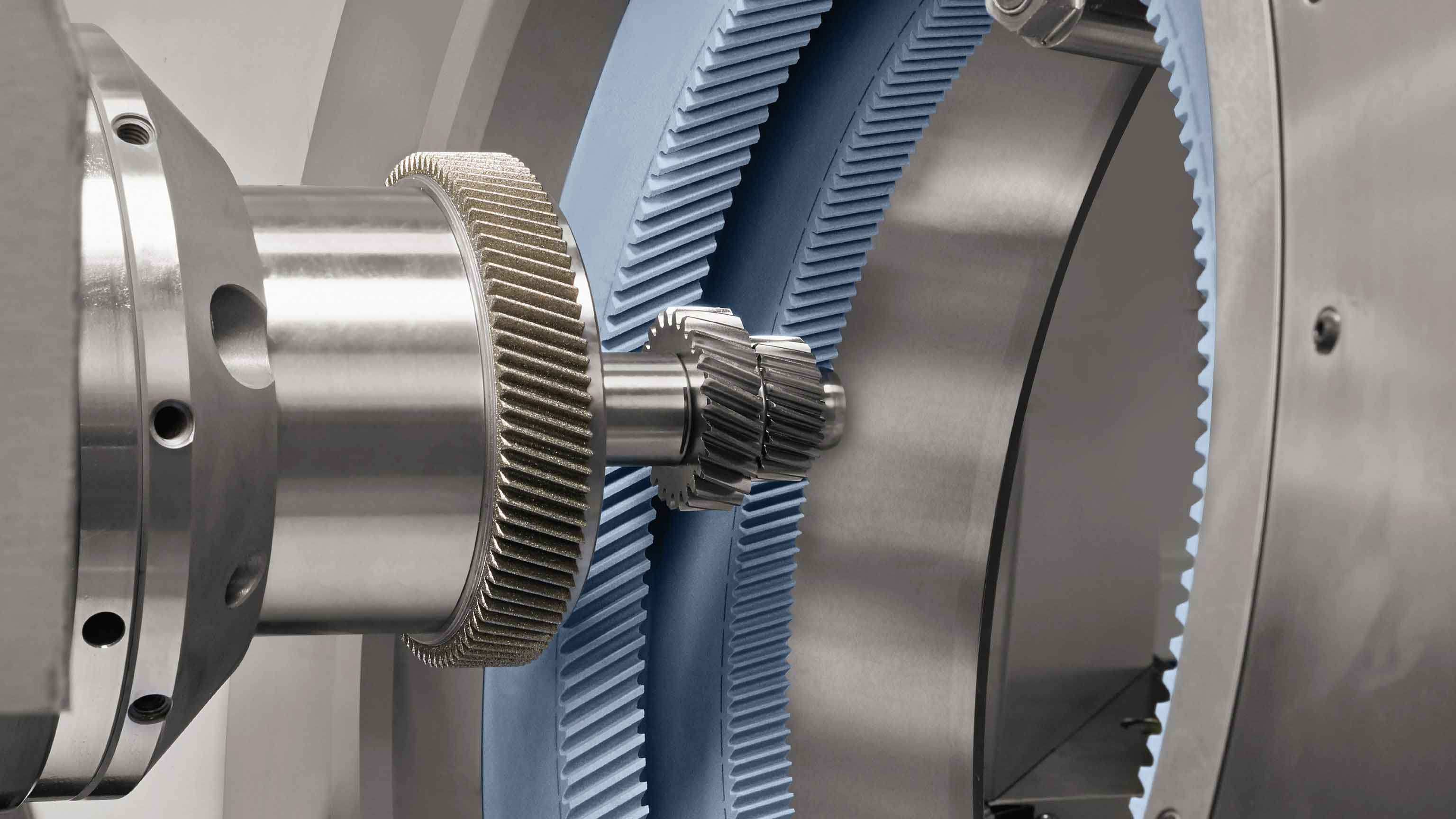
The new bevel gear – roller flat disk transmission combines the bevel gear and roller flat disk transmission mechanisms. The bevel gear part is mainly responsible for changing the transmission ratio, while the roller flat disk part is used for smooth torque transmission. Through the meshing of the bevel gears and the rolling of the rollers on the flat disk, the power is transmitted and the speed is changed.
| Component | Function |
|---|---|
| Bevel Gear | Change the transmission ratio |
| Roller Flat Disk | Transmit torque smoothly |
2.2 Dynamic Modeling
2.2.1 Bevel Gear Part
Considering the influence of load changes on the transmission ratio, the load coefficient is introduced. The transmission ratio of the bevel gear can be expressed as , where and are the numbers of teeth of the two bevel gears, and is a nonlinear function related to the output torque.
2.2.2 Roller Flat Disk Part
When the roller rolls on the flat disk, it is mainly affected by the friction force . By introducing the rolling resistance coefficient , the rolling resistance moment can be expressed as , where is the roller linear velocity, is the roller angular acceleration, is the friction coefficient, is the material density, and is the roller radius.
2.2.3 Overall Dynamic Equation
Integrating the dynamic equations of the bevel gear and roller flat disk parts, the dynamic equation of the entire transmission is obtained as , where is the moment of inertia of the output shaft, and and are the input and output shaft torques, respectively.
3. Fuzzy PID Control
3.1 Fuzzy Condition Setting
3.1.1 Input Variables
The error is defined as the difference between the actual speed and the set speed, which reflects the current control deviation of the system. The error change rate is the change rate of the error over time, which reflects the change trend of the system deviation.
3.1.2 Fuzzy Sets and Membership Functions
Fuzzy sets such as {NB, NM, NS, Z, PS, PM, PB} are defined for the error and the error change rate .
3.1.3 Fuzzy Rule Base
Based on expert experience or system dynamic characteristics, a fuzzy rule base is established. The rules are usually in the form of “If is and is , then is , is , is “.
3.1.4 Fuzzy Inference and Defuzzification
The fuzzy inference engine is used for fuzzy inference to determine the adjustment values of the PID parameters according to the input and . Then, the weighted average method is used to convert the output of the fuzzy inference into accurate PID parameter adjustment amounts.
3.2 Controller Design
The output shaft speed deviation and deviation change rate are selected as the inputs of the fuzzy controller, and the output is the parameter adjustment amounts , , and . The designed fuzzy controller structure is shown in Figure 1.
[Insert a diagram of the fuzzy controller structure here]
The system deviation and deviation change rate need to be fuzzified and mapped to the fuzzy domain. Quantization factors are determined according to the basic domain and the discrete fuzzy domain.
3.3 Control Quantity Output
After the fuzzy PID control is completed, the fuzzy rules are designed, and the fuzzy output is converted into accurate PID parameter adjustment amounts through the defuzzification method. Then, the updated parameters are used for PID control calculation to obtain the control quantity. The control quantity is converted into an adjustment command for the input shaft speed or torque and sent to the transmission actuator to achieve constant control of the output shaft speed.
4. Simulation Experiment
4.1 Experimental Setup
4.1.1 Experimental Objects
The new bevel gear – roller flat disk transmission selected in this experiment consists of a bevel gear transmission part and a roller flat disk continuously variable transmission part. The overall speed range is set from 500 r/min to 3000 r/min, and the transmission efficiency can reach more than 95% under ideal working conditions.
4.1.2 Modeling Parameters
The modeling parameters of the transmission simulation model are set as shown in Table 2.
| Parameter | Configuration |
|---|---|
| Input Bevel Gear 1 Teeth | 50 |
| Bevel Gear 3/4 Teeth | 55 |
| Bevel Gear 5/6 Teeth | 65 |
| Input Bevel Gear 2 Teeth | 60 |
| Roller Radius/mm | 50 |
| Flat Disk Radius/mm | 70 |
| Rolling Resistance Coefficient | 0.15 |
| Load Coefficient | 0.01 |
| Number of Neurons Added | 5 |
| Maximum Number of Neurons | 100 |
| PID Proportional Coefficient | 0.1 |
| Integral Time Constant | 0.0004 |
| Differential Time Constant | 5.95 |
4.2 Control Methods Comparison
Two conventional transmission constant speed control methods, namely the MPC-based method and the ant colony algorithm-based method, are selected as comparison objects. The three control methods are used to simulate the speed output control of the same transmission model, and the actual control effects are compared.
4.3 Experimental Results
4.3.1 Speed Tracking Curves
The simulation speed output curves of the transmission under different control methods are shown in Figure 3. It can be seen that the proposed control method can achieve speed output control within a shorter adjustment time under different load torque conditions.
[Insert the speed tracking curves under different load torques here]
4.3.2 Overshoot Comparison
The comparison results of the overshoot of different control methods are shown in Table 3. It can be clearly seen that the proposed fuzzy PID control method has significantly better control accuracy than the two conventional control methods, and the instantaneous maximum deviation value of the regulated quantity is lower.
| Experimental Group Number | Design Method | Conventional Method A | Conventional Method B |
|---|---|---|---|
| 01 | 3.15 | 4.24 | 5.57 |
| 02 | 3.36 | 4.52 | 5.54 |
| 03 | 3.25 | 4.36 | 5.61 |
| 04 | 3.19 | 4.21 | 5.50 |
| 05 | 3.11 | 4.26 | 4.65 |
| 06 | 3.26 | 4.34 | 4.60 |
| 07 | 3.16 | 4.22 | 5.61 |
| 08 | 3.05 | 4.45 | 4.56 |
| 09 | 3.31 | 4.57 | 5.10 |
| 10 | 3.10 | 4.53 | 5.54 |
| 11 | 3.36 | 4.48 | 5.50 |
| 12 | 3.22 | 4.31 | 5.12 |
5. Conclusion
In this paper, the fuzzy PID control method for the constant speed output of the new bevel gear – roller flat disk transmission is studied in depth. Through accurate transmission modeling and reasonable fuzzy PID controller design, the control accuracy and stability of the transmission are effectively improved. The experimental results also prove the superiority of this method. In future research, further optimization of the control method can be considered to meet the higher requirements of different application scenarios.