
In order to realize the new gear cutting method on the general milling machine, a device which can make the gear blank rotate synchronously with the tool feed is needed. Therefore, a prototype of feed synchronizer is developed. The feed synchronizer installed on the worktable of the milling machine is shown in Figure 1.
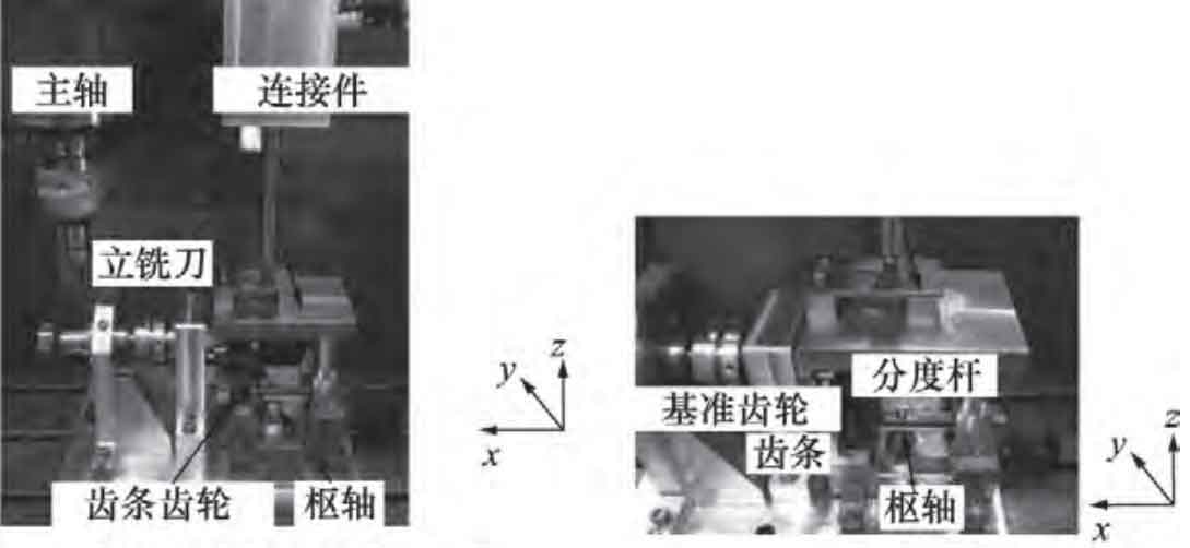
The feed synchronizer is installed on the worktable of the milling machine, as shown in Fig. 1a. The Y direction is the feed direction of the milling cutter, which is mechanically connected to the gear rotating shaft through the rack and pinion transmission mechanism, as shown in Fig. 1b. The movement in X and Z directions is separated from the gear rotating shaft, and an indexing mechanism is installed. The principle of the indexing mechanism is shown in Figure 2.
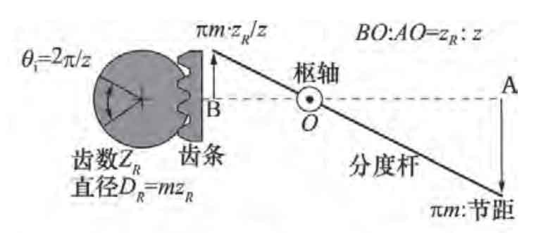
The indexing rod can rotate on the pivot. In addition, the position of the pivot is located by dividing the position Bo: Ao = Zr: Z, where Zr is the number of teeth of the reference gear. When point a moves along the pitch length, point B moves π m · Zr / Z. Point B is connected to the rack, which meshes with the reference gear. Finally, the reference gear rotates θ i. As shown in the formula.

Where: Dr is the diameter of the reference gear; Zr is the number of teeth of the reference gear. This means that the number of teeth can be changed by adjusting the position of the pivot. The cutting test is carried out with the feed synchronization device, as shown in Fig. 3.

The cutter is a conical end mill with a half cone angle of 20 °, which is the same as the pressure angle. The workpiece material is engineering plastic, and the gear parameters are: modulus 2.5 mm, pressure angle 20 °, number of teeth 31.
In order to verify the effectiveness of the proposed method, the gear processed by the proposed method (general milling machine) is compared with the gear processed by hobbing machine. The physical comparison of the two gears is shown in Figure 4.

In Figure 4, the left gear is the gear machined by gear hobbing machine, and the right gear is the gear machined by the proposed method. The cutting time is about 2 hours because all operations are done manually. Some tooth profile errors of the two gears are shown in Figure 5.

The tooth profiles of the two gears are very similar, and the maximum error of the tooth profile is 0.05 mm. These results show that the proposed gear cutting method can effectively machine involute gears. In this machining test, the cutting depth was set to 2.5 mm. When the number of teeth is the same, another module gear can be cut by changing only the cutting depth. Variable modulus gear cutting samples on the same gear blank at M = 1, 1.5, 2 and 2.5 mm( α = 20 °) as shown in Figure 6.

It can be seen that the proposed gear cutting method can process gears with different modulus and teeth with different number of teeth only using a single cutting tool. In addition, the cutting of circular arc tooth line gear is shown in Fig. 7.

It can be seen from Fig. 7 that the machined tooth trace forms a sinusoidal curve, which illustrates the applicability of the proposed method in the machining of circular arc tooth line gear.
To sum up, the proposed gear cutting method can realize gear machining with various gear parameters. Although the productivity is reduced, due to less demand, the proposed method can meet the needs of special types of gear processing with reasonable cost and better accuracy.