
Firstly, the engagement process of the gear is analyzed. The engagement state and force diagram of the gear is shown in Figure 2.2, where the overlap degree of the spur gear is 1.327.The overlap of the spur gear at the torque Tp is 1.327.
Drive gear rotates clockwise around axis Op P under the action of torque Tp acting as P. Load of driven gear is Tg, load of dynamic gear is Tg, load of dynamic gear is Tg, load of rotary gear is Tg, Og around axis, counter-clockwise rotation around axis Og.In the direction of engagement line (LOA), P and G are the tangential points of action line and base circle of main and driven gears respectively. When the pair of gears 1 is meshed at point A, the pair engages at point D until point E is out of engagement. At this time, the pair of gears 1 just enters the single-tooth engagement area at point B until point D, and a new pair of gears is meshed at point A.
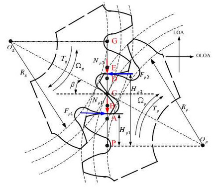
For force analysis of active gear, gear tooth 1 is under positive pressure Np1 in AD section. For force analysis of active gear, gear tooth 1 is under positive pressure Np1, P1 in AD section and gear tooth 2 is under positive pressure Np2 and P2 in DE section. At the same time, the tooth surface friction corresponding to positive pressure of gear tooth 1 is Fp1, while the tooth surface friction corresponding to positive pressure of gear tooth 1 is Fp1 and Fp 2 respectively.Fp2, p2, acting on the vertical direction of engagement line (OLOA), in which Fp1 is in the vertical direction (OLOA), where Fp1 is reversed after P1 passes through node C at engagement point, and friction is opposite to axial Op after passing through node C at engagement point. Fp1 and Hp and Hp2 are respectively the force arms of friction with respect to axial Op.