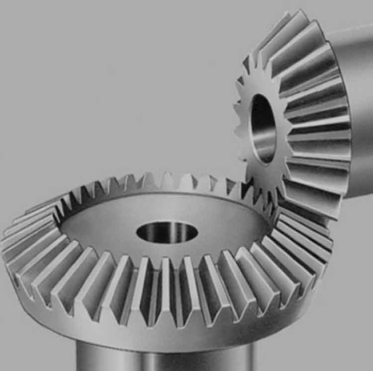
Gear geometry and tooth contact analysis are crucial aspects of designing and optimizing straight bevel gears to ensure efficient power transmission and durability. These analyses help engineers understand how the gear teeth interact during meshing and how to achieve the desired performance characteristics. Let’s delve into gear geometry and tooth contact analysis for straight bevel gears:
Gear Geometry:
- Pitch Cones: Straight bevel gears have pitch cones, which are imaginary cones that coincide at the pitch point. The pitch cones determine the gear ratio and orientation.
- Pitch Circle and Pitch Diameter: The pitch circle is a theoretical circle on the gear that is tangent to the pitch cones. The pitch diameter is the diameter of the pitch circle and defines the gear size.
- Diametral Pitch (DP): Diametral pitch is the number of teeth per inch of pitch diameter. It represents the size of the gear teeth and affects gear tooth dimensions.
- Addendum and Dedendum: The addendum is the distance from the pitch circle to the top of the gear tooth, while the dedendum is the distance from the pitch circle to the bottom of the tooth.
- Pressure Angle: The pressure angle is the angle between the line of action (line connecting the pitch point to the gear’s center) and the tangent to the pitch circle. Common pressure angles are 20° and 14.5°.
Tooth Contact Analysis:
- Tooth Contact Pattern: Tooth contact analysis involves examining the contact pattern between the gear teeth during meshing. A well-centered and evenly distributed tooth contact pattern is desirable for smooth operation and even load distribution.
- Contact Ratio: The contact ratio is the ratio of the length of the tooth contact to the circular pitch. It indicates the number of teeth in contact at any given moment during meshing.
- Contact Ellipse: In tooth contact analysis, the tooth contact pattern is often represented as an ellipse. The goal is to achieve an optimal contact ellipse for uniform load distribution.
- Contact Pattern Adjustment: Engineers can adjust the contact pattern by modifying gear geometry, such as adding crowning, tip relief, or profile shifting. These adjustments optimize tooth contact and minimize localized wear.
- Load Distribution: Proper gear design and tooth contact analysis ensure even load distribution across the gear teeth, reducing the risk of premature failure.
- Lubrication: Adequate lubrication is crucial to minimize friction and wear during gear operation. It enhances the gear’s efficiency and prolongs its lifespan.
Gear geometry and tooth contact analysis are typically performed using specialized software and simulation tools. These analyses allow engineers to optimize gear design, predict performance, and ensure that the gears meet the required standards for efficiency, noise reduction, and durability. By understanding gear geometry and tooth contact characteristics, engineers can produce high-quality straight bevel gears that deliver reliable and efficient power transmission in various applications.
