
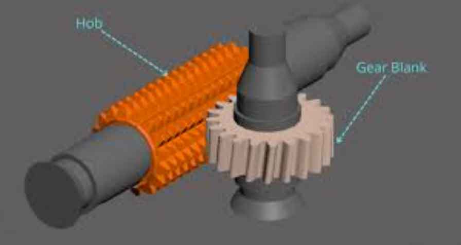
I studied the gear hobbing process of cycloidal gears used in RV reducers because the cycloidal gear is a core functional component and its tooth profile accuracy directly controls transmission accuracy, torsional stiffness, and vibration behavior. In my research, I treated gear hobbing as a non-free, intermittent, multi-edge generating process. The cycloidal gear contains multiple hollow holes for assembly, so its stiffness is not uniform. During gear hobbing, the cutting force can cause elastic deformation of the thin rim, especially in the weak-rigidity zone, and this deformation changes the effective cutting depth and may produce a final tooth profile outside the required tolerance. My aim was to derive the cycloidal gear profile and hob edge equations, build geometric models for gear hobbing, simulate cutting force by finite element method, validate the force model, and analyze cutting deformation in different rigidity zones and at different machining stages.
Geometric Modeling for Gear Hobbing
I used the enveloping method and the gear meshing principle to describe the cycloidal gear flank. The pin wheel is fixed to one coordinate system and the cycloidal gear is fixed to another. When the base circle of the cycloidal gear rolls inside the base circle of the pin wheel, a short-amplitude epicycloid equidistant curve is formed. I expressed the cycloidal gear tooth profile in terms of the rotation angle \(\varphi_1\), the pin wheel radius \(R_z\), the eccentricity \(e\), the pin radius \(r_z\), and an auxiliary angle \(\gamma\). The profile equations I used can be summarized as
$$x_z = R_z \cos\varphi_1 – e\cos(z_1\varphi_1) – r_z \cos(\varphi_1+\gamma)$$
$$y_z = R_z \sin\varphi_1 – e\sin(z_1\varphi_1) – r_z \sin(\varphi_1+\gamma)$$
where
$$\gamma = \arctan\frac{\sin\varphi_1}{\dfrac{R_z}{r_1 z_1}-\cos\varphi_1}$$
and \(z_1\) is the number of cycloidal gear teeth. The corresponding pin wheel profile can be written as
$$x_p = r_z \sin\gamma,\qquad y_p = R_z – r_z \cos\gamma.$$
For the gear hobbing tool, I treated the hob as a conjugate worm-like cutter. The normal blade profile of the cycloidal gear hob is the conjugate curve of the cycloidal gear profile. I transformed the gear profile into the hob coordinate system through a rack meshing relation. The transformation can be written in homogeneous form as
$$\begin{bmatrix}X_C’\\Y_C’\\1\end{bmatrix}
=
\begin{bmatrix}
\cos\eta & -\sin\eta & X_1\\
\sin\eta & \cos\eta & r_1\\
0 & 0 & 1
\end{bmatrix}
\begin{bmatrix}X_1\\Y_1\\1\end{bmatrix}$$
where \(\eta\) is the rolling angle of the rack relative to the gear. To satisfy the conjugate condition, I imposed
$$\eta = \frac{\pi}{2}+\gamma-\arccos\frac{X_1\cos\gamma+Y_1\sin\gamma}{r_1}.$$
The main parameters I used for the cycloidal gear and the hob are listed in Table 1 and Table 2.
| Cycloidal gear parameter | Symbol | Value or relation |
|---|---|---|
| Pin wheel radius | \(R_z\) | 82 mm |
| Eccentricity | \(e\) | 1.5 mm |
| Cycloidal gear base radius | \(r_1\) | 38.5 mm |
| Pin wheel base radius | \(r_2\) | 40 mm |
| Pin radius | \(r_z\) | 7 mm |
| Rotation angle range | \(\varphi_1\) | \(10^\circ \le \varphi_1 \le 360^\circ\) |
| Hob parameter | Symbol | Relation |
|---|---|---|
| Blade height | \(h_0\) | \(h_0 = 2e\) |
| Normal pitch | \(p_n\) | \(p_n = 2\pi r_a / z_1\) |
| Module-like parameter | \(m\) | \(m = p_n/\pi\) |
| Pitch diameter | \(d_0\) | \(d_0 = d – 2h_0 = d – 4e\) |
| Spiral angle | \(\gamma_z\) | \(\sin\gamma_z = m z_0 / d_0\) |
| Axial pitch | \(p_x\) | \(p_x = p_n/\cos\gamma_z\) |
I then analyzed the kinematic chain of gear hobbing. The motion of the hob relative to the workpiece includes hob rotation, workpiece rotation, axial feed, radial feed, tangential feed, and hob swivel. I represented these motions by homogeneous transformation matrices. The overall transformation from the hob coordinate system to the workpiece coordinate system is
$$M_{61}=M_{65}M_{54}M_{43}M_{32}M_{21}.$$
For a point \(P\) fixed to the hob, its position in the workpiece coordinate system is
$$r_{pw}^{(1)} = M_{16} r_{ph}^{(6)}.$$
The relative velocity between the hob and the workpiece at the contact point is
$$v_{phw}^{(2)} = v_{ph}^{(2)} – v_{pw}^{(2)}.$$
I expanded the velocity expression by considering the angular velocity of the hob, the angular velocity of the workpiece, the axial feed velocity \(v_a\), the radial feed velocity \(v_r\), and the tangential feed velocity \(v_t\). A reduced form of the relative velocity in the workpiece coordinate system is
$$v_{phw}^{(2)} =
\begin{bmatrix}
-y_2 w_2 – a w_1 \sin\gamma_{an} + v_t \cos\gamma_{an}\\
x_2 w_2 – z_2 w_1 \cos\gamma_{an} + h_0 w_1 \cos\gamma_{an} + v_a \sin\gamma_{an}\\
x_2 w_1 \sin\gamma_{an} – z_2 w_1 \cos\gamma_{an} + v_r
\end{bmatrix}.$$
This kinematic description allowed me to build the spatial surface cluster swept by the hob blades. For the \(i\)-th cutting edge on the hob, I wrote
$$r_i^{(1)} = M_{61} M_{hi} r_i^{(hi)},$$
where \(M_{hi}\) defines the angular position of the blade on the hob. The full blade space trajectory surface cluster can be expressed as
$$G_i(\varphi)=R_x R_z T_z r_i^{(hi)}.$$
By intersecting this surface cluster with the workpiece blank, I obtained the tooth slot model for any stage of gear hobbing. I divided the axial feed process into three stages: the cut-in stage, the full-cutting stage, and the cut-out stage. The full-cutting stage occupies most of the gear hobbing time and is not influenced by the upper and lower end faces of the workpiece. Therefore, I focused my cutting force and deformation analysis on the full-cutting stage, while treating the cut-in and cut-out stages as boundary-controlled special cases.
Undeformed Chip Geometry in Gear Hobbing
I calculated the undeformed chip geometry from the swept surfaces of adjacent hob blades. The normal vector of the \(i\)-th blade surface cluster is
$$n^{(hi)} = \frac{\partial G_i}{\partial i} \times \frac{\partial G_i}{\partial \varphi}.$$
The normal chip thickness can be estimated from the distance between adjacent surface clusters along the normal direction. I wrote the thickness relation as
$$h^{(hi)} =
\frac{1}{\left\|\dfrac{\partial G_i}{\partial i}\times\dfrac{\partial G_i}{\partial\varphi}\right\|}
\left[
\left(\frac{\partial G_{i+1}}{\partial (i+1)}\times\frac{\partial G_{i+1}}{\partial\varphi}\right)
–
\left(\frac{\partial G_i}{\partial i}\times\frac{\partial G_i}{\partial\varphi}\right)
\right].$$
The chip volume was obtained by integrating the thickness over the engagement area:
$$V = \iint h^{(hi)}
\left\|\frac{\partial G_i}{\partial i}\times\frac{\partial G_i}{\partial\varphi}\right\|
\,di\,d\varphi.$$
The average chip thickness was then
$$h_{avg}=\frac{V}{A}.$$
Within one cutting cycle of a single tooth slot in the full-cutting stage, I identified eight representative blade positions. The undeformed chip length did not change dramatically within one cutting cycle. The longest chip was about 13 mm and the shortest was about 11.5 mm. The chip width and thickness were larger at the beginning and end of the cycle and smaller in the middle. The maximum chip thickness ranged from about 0.15 mm to about 0.35 mm. These values were important because the cutting force in gear hobbing depends strongly on chip thickness and chip width.
| Blade position in one cycle | Relative chip width | Relative chip thickness | Approximate maximum thickness |
|---|---|---|---|
| 1 | Wide | Thick | About 0.35 mm |
| 2 | Wide | Thick | About 0.35 mm |
| 3 | Narrow | Medium | About 0.20 mm |
| 4 | Narrow | Medium | About 0.18 mm |
| 5 | Narrow | Medium | About 0.16 mm |
| 6 | Narrow | Thin | About 0.15 mm |
| 7 | Medium | Medium | About 0.25 mm |
| 8 | Wide | Thick | About 0.35 mm |
Finite Element Modeling of Gear Hobbing Cutting Force
I simplified the gear hobbing model to a single hob tooth and a single tooth slot. This simplification was justified because the cutting deformation in a thin cycloidal gear is mainly caused by the local cutting force, while the reverse effect of deformation on the cutting force is smaller than the forward effect of force on deformation. The simplified model still preserved the actual cutting motion, the actual tooth slot geometry, and the actual contact conditions. I used a Lagrangian formulation for the large deformation and high strain-rate problem. The control equation was
$$\int_{V_0} B^T S\,dV_0
=
\int_{V_0} N^T f_i\,dV_0
+
\int_{A_0} N^T F_i\,dA_0,$$
where \(B\) is the strain-displacement matrix, \(N\) is the shape function matrix, \(S\) is the stress tensor, \(f_i\) is the body force, and \(F_i\) is the surface traction.
I assigned the workpiece material properties of 25CrMo4 steel and the hob material properties of M35 high-speed steel. The workpiece Poisson ratio was 0.3 and the density was \(7.85\times10^{-6}\,\text{kg/mm}^3\). The hob Poisson ratio was 0.23, the thermal conductivity was \(30\,\text{W/(m K)}\), the specific heat was \(15\,\text{J/(kg K)}\), and the density was \(8.14\times10^{-6}\,\text{kg/mm}^3\). The temperature-dependent elastic modulus, thermal expansion, thermal conductivity, and specific heat of the workpiece are summarized in Table 3.
| Temperature (°C) | Young’s modulus (MPa) | Thermal expansion (\(10^{-5}\)/K) | Thermal conductivity (W/(m K)) | Specific heat (J/(kg K)) |
|---|---|---|---|---|
| 20 | 212000 | 1.19 | 41.7 | 6.61885 |
| 100 | 207000 | 1.25 | 43.4 | 3.8936 |
| 200 | 199000 | 1.31 | 41.4 | 4.18405 |
| 300 | 192000 | 1.36 | 39.1 | 4.4588 |
| 400 | 184000 | 1.41 | 36.7 | 4.79635 |
| 500 | 175000 | 1.49 | 34.1 | 5.31445 |
| 600 | 164000 | 1.49 | 34.1 | 6.1073 |
| 1500 | 69440 | 1.49 | 34.1 | 6.1073 |
For the flow stress of the workpiece, I used a constitutive relation that couples strain hardening, strain-rate hardening, and thermal softening. A compact form is
$$\sigma = (A+B\varepsilon^n)\left(1+C\ln\frac{\dot\varepsilon}{\dot\varepsilon_0}\right)\left[1-(T^*)^m\right],$$
where
$$T^* = \frac{T-T_{room}}{T_{melt}-T_{room}}.$$
I used \(A=1200\), \(B=891\), \(C=0.02\), \(n=0.2\), \(m=0.64\), \(\dot\varepsilon_0=1\), \(T_{room}=293\,\text{K}\), and \(T_{melt}=1800\,\text{K}\). For chip separation, I used a physical fracture criterion based on equivalent plastic strain:
$$\int_0^{\bar\varepsilon_f} \frac{d\bar\varepsilon}{\sigma^*} = C_4,$$
where \(\sigma^*\) is a stress-triaxiality-related parameter and \(C_4\) is a critical damage value. I set the node separation condition when the local tensile stress exceeded a small threshold. For the contact between the chip and the rake face, I used a pressure-dependent friction law:
$$\tau_f =
\begin{cases}
k_{chip}, & \mu\sigma_n \ge k_{chip},\\
\mu\sigma_n, & \mu\sigma_n < k_{chip},
\end{cases}$$
where \(k_{chip}\) is the shear flow stress of the chip, \(\mu\) is the friction coefficient, and \(\sigma_n\) is the normal stress. This law allowed me to represent both the sticking region near the cutting edge and the sliding region farther along the rake face.
I meshed the workpiece with tetrahedral elements. The total number of nodes was 75264, the number of surface facets was 48000, and the number of elements was 67088. I refined the mesh in the cutting zone and near the contact region. The coarse mesh size was about 0.1 mm, and the refined mesh size was about 0.02 mm. I fixed the bottom of the workpiece in the axial direction and applied symmetry constraints on the cut faces. The cutting environment was oil cooling, and I used a heat convection coefficient of \(2125\,\text{W/(m K)}\). The hob was treated as a rigid body because its stiffness is much higher than that of the workpiece and because the simulation time was short.
To validate the gear hobbing force model, I compared my simulation with experimental data from an independent gear hobbing test. The validation workpiece was a 25CrMo steel blank with a length of 20 mm, an outer diameter of 144 mm, and an inner hole diameter of 40 mm. The hob was an involute gear hob with an outer diameter of 75 mm, one start, 14 gashes, a spiral angle of \(4.917^\circ\), a pressure angle of \(20^\circ\), a rake angle of \(0^\circ\), and a module of 4 mm. The cutting conditions were a spindle speed of 300 rpm and 900 rpm and an axial feed of 1.667 mm/r. The comparison is shown in Table 4.
| Case | Speed \(n\) (r/min) | Axial feed \(a_f\) (mm/r) | Simulated axial force (N) | Experimental axial force (N) | Axial error (%) | Simulated radial force (N) | Experimental radial force (N) | Radial error (%) |
|---|---|---|---|---|---|---|---|---|
| 1 | 300 | 1.667 | 556.4 | 609.1 | 8.64 | 76.05 | 84.04 | 10.5 |
| 2 | 900 | 1.667 | 571.7 | 624.8 | 9.28 | 81.6 | 89.9 | 6.79 |
The simulated axial and radial forces were in the same order of magnitude as the experimental values, and the trends with respect to cutting speed were consistent. The maximum axial force error was about 9.28%, and the maximum radial force error was about 10.5%. I considered this agreement sufficient to validate the finite element model for gear hobbing cutting force prediction.
Cutting Force Analysis in Gear Hobbing
I analyzed the cutting force for different blade positions within the same tooth slot. The cutting force curves showed high-frequency fluctuations because of non-uniform material softening and non-uniform plastic deformation. In general, a wider chip produced a lower fluctuation frequency and a larger fluctuation amplitude, while an increasing uncut chip thickness first reduced the fluctuation and then increased it after a critical value. For the three representative blade positions I studied, the chip thickness was about 0.20 mm for blade 3, about 0.15 mm for blade 6, and about 0.35 mm for blade 8. Blade 8 produced the highest and most stable force peak, so I selected blade 8 for detailed gear hobbing force analysis.
For a cutting speed of 600 r/min and an axial feed of 0.5 mm/r, the axial force rose rapidly in the first 2 ms to about 800 N, remained relatively stable from about 2 ms to 5 ms, and then decreased until the tool left the workpiece. The radial force rose quickly in the first 1.6 ms to about 400 N and then decreased gradually. The tangential force first rose to about 25 N, then showed a short drop caused by the tool-workpiece yielding effect before the chip was fully formed, then increased slowly to a peak of about 80 N between 4 ms and 6 ms, and finally decreased. The differences in the peak times occurred because the chip thickness and chip width changed at different rates, and the tangential force was more sensitive to chip width, while the axial and radial forces were more sensitive to chip thickness.
I then studied the influence of gear hobbing parameters on cutting force. The selected cutting speeds were 300, 450, 600, 750, and 900 r/min. The selected axial feeds were 0.25, 0.5, 0.75, and 1.0 mm/r. The results for the axial force are summarized in Table 5, and the results for different force components under different axial feeds are summarized in Table 6.
| Cutting speed \(n\) (r/min) | Axial cutting force (N) |
|---|---|
| 300 | 791 |
| 450 | About 799 |
| 600 | About 811 |
| 750 | About 824 |
| 900 | 834 |
| Axial feed \(a_f\) (mm/r) | Axial force (N) | Radial force (N) | Tangential force (N) |
|---|---|---|---|
| 0.25 | 803.4 | 324.4 | 51.0 |
| 0.50 | 811.1 | 358.1 | 52.0 |
| 0.75 | 823.5 | 408.0 | 54.7 |
| 1.00 | 914.4 | 553.5 | 82.0 |
I found that the axial cutting force increased only slightly when the cutting speed increased from 300 r/min to 900 r/min. The increase was about 42 N. In contrast, the axial cutting force increased by about 91 N when the axial feed increased from 0.25 mm/r to 1.0 mm/r. Therefore, the axial feed had a stronger influence on the axial cutting force than the cutting speed. The radial and tangential forces showed a similar trend. For both radial and tangential forces, the axial feed of 0.75 mm/r acted as a threshold. When the axial feed exceeded 0.75 mm/r, the chip thickness became large enough to cause a sharp increase in cutting force. This behavior is important for gear hobbing because excessive axial feed can rapidly increase the load on the weak-rigidity region of the cycloidal gear.
Finite Element Modeling of Cutting Deformation in Gear Hobbing
I analyzed the deformation of the cycloidal gear during gear hobbing by static finite element analysis. The cycloidal gear contains three circular holes and three trapezoidal holes. The trapezoidal-hole region has the thinnest rim and the lowest stiffness, so I defined it as the weak-rigidity zone. The circular-hole region has a thicker rim and higher stiffness, so I defined it as the medium-rigidity zone. The region between the circular hole and the trapezoidal hole has the highest stiffness, so I defined it as the strong-rigidity zone. The deformation direction was mainly radial and circumferential because the axial deformation does not directly change the cutting depth in gear hobbing. The radial deformation changes the effective cutting depth and can further change the cutting force. Because gear hobbing is an intermittent cutting process, each tooth slot experiences repeated force loading, so deformation control is critical for profile accuracy.
| Zone | Structural feature | Relative stiffness | Expected deformation |
|---|---|---|---|
| Weak-rigidity zone | Trapezoidal hole region | Lowest | Largest |
| Medium-rigidity zone | Circular hole region | Medium | Medium |
| Strong-rigidity zone | Between holes | Highest | Smallest |
I modeled the clamping condition according to the actual gear hobbing fixture. The center hole of the cycloidal gear was mounted on a mandrel, so I constrained the radial and circumferential displacements of the center hole. The bottom of the gear rim was supported by the fixture, so I constrained the axial displacement of the rim. A positioning pin was used in the circular holes, but I did not apply a fully fixed constraint there because the pin mainly provides locating rather than rigid clamping during cutting. I applied the cutting force as a point-surface coupling load on the tooth slot surface. The axial force was aligned with the gear axis, the radial force was normal to the cutting surface, and the tangential force was perpendicular to both. I used tetrahedral elements and refined the mesh near the tooth slot and the outer rim.
I selected four representative models for the deformation analysis: one from the cut-in stage, two from the full-cutting stage, and one from the cut-out stage. The cutting speed was 600 r/min, and the axial feed was 0.5 mm/r. The deformation results for the weak-rigidity zone are summarized in Table 7.
| Cutting stage | Maximum deformation in weak-rigidity zone (\(\mu\)m) |
|---|---|
| Cut-in stage | 8.19 |
| Full-cutting stage, early moment | 9.71 |
| Full-cutting stage, late moment | 10.47 |
| Cut-out stage | 9.00 |
The deformation increased from the cut-in stage to the late full-cutting stage and then decreased during the cut-out stage. The reason is that the chip thickness and chip volume increase as the hob enters the full-cutting stage and reach a maximum near the end of the full-cutting stage. The cutting force follows the same trend, so the elastic deformation of the thin rim reaches its maximum at the late full-cutting stage. The decrease in the cut-out stage is faster than the increase in the cut-in stage because the chip thickness decreases rapidly as the hob exits the workpiece.
I also studied different tooth slots in the weak-rigidity zone at the same cutting stage. The maximum deformation for slots 1 through 6 is listed in Table 8.
| Tooth slot number | 1 | 2 | 3 | 4 | 5 | 6 |
|---|---|---|---|---|---|---|
| Maximum deformation (\(\mu\)m) | 10.79 | 11.22 | 11.29 | 11.05 | 10.87 | 10.48 |
The deformation first increased and then decreased as the cutting moved from slot 1 to slot 6. The maximum deformation appeared near slot 3, where the radial cutting force was directed toward the trapezoidal hole and the local rim stiffness was lowest. Slots 5 and 6 were closer to the strong-rigidity zone, so their deformation was smaller. This result confirms that the local stiffness distribution of the cycloidal gear strongly affects the deformation during gear hobbing.
I then analyzed the effect of gear hobbing parameters on the weak-rigidity zone. The maximum deformation for different cutting speeds is shown in Table 9, and the maximum deformation for different axial feeds is shown in Table 10.
| Cutting speed \(n\) (r/min) | Maximum deformation in weak-rigidity zone (\(\mu\)m) |
|---|---|
| 300 | 10.69 |
| 450 | 10.73 |
| 600 | 11.23 |
| 750 | 11.29 |
| Axial feed \(a_f\) (mm/r) | Maximum deformation in weak-rigidity zone (\(\mu\)m) |
|---|---|
| 0.25 | 11.03 |
| 0.50 | 11.23 |
| 0.75 | 11.75 |
| 1.00 | 12.74 |
The deformation increased with both cutting speed and axial feed. However, the influence of axial feed was greater. The maximum deformation increased by only about 0.6 \(\mu\)m when the cutting speed increased from 300 r/min to 750 r/min, but it increased by about 1.7 \(\mu\)m when the axial feed increased from 0.25 mm/r to 1.0 mm/r. The axial feed directly controls the uncut chip thickness, and a larger chip thickness causes a larger cutting force and a larger elastic deformation. In gear hobbing of a thin cycloidal gear, controlling the axial feed is therefore more effective than reducing the cutting speed for deformation control.
I also analyzed the medium-rigidity zone. The maximum deformation at different cutting stages was about 10.20 \(\mu\)m, but most of the medium-rigidity zone deformed by only about 4 to 7 \(\mu\)m. The maximum deformation still occurred in the weak-rigidity zone even when the cutting force was applied in the medium-rigidity zone. This means that the weak-rigidity zone dominates the global deformation field of the cycloidal gear during gear hobbing. The deformation results for different cutting speeds and axial feeds in the medium-rigidity zone are summarized in Table 11 and Table 12.
| Cutting speed \(n\) (r/min) | Maximum deformation in medium-rigidity zone (\(\mu\)m) |
|---|---|
| 300 | 10.11 |
| 450 | 10.31 |
| 600 | 10.47 |
| 750 | 10.66 |
| Axial feed \(a_f\) (mm/r) | Maximum deformation in medium-rigidity zone (\(\mu\)m) |
|---|---|
| 0.25 | 10.33 |
| 0.50 | 10.47 |
| 0.75 | 10.93 |
| 1.00 | 11.44 |
The medium-rigidity zone followed the same parameter trend as the weak-rigidity zone, but the absolute deformation was smaller because the circular-hole region has a thicker rim and higher local stiffness. Even so, the maximum deformation in the whole gear still appeared in the weak-rigidity zone. Therefore, any deformation compensation strategy for gear hobbing of this cycloidal gear should first target the trapezoidal-hole region.
Radial and Circumferential Deformation Laws in Gear Hobbing
I evaluated the radial and circumferential deformation of the cycloidal gear tooth profile after gear hobbing. For a point \(P(X,Y,Z)\) on the gear, the radial distance from the gear axis is
$$R_P = \sqrt{X^2+Y^2}.$$
After deformation, the point moves to \(P'(X’,Y’,Z’)\), and the new radial distance is
$$R_P’ = \sqrt{(X’)^2+(Y’)^2}.$$
The radial deformation is
$$\Delta R = \sqrt{(X’)^2+(Y’)^2} – \sqrt{X^2+Y^2}.$$
The circumferential deformation can be approximated from the angular displacement as
$$\Delta l \approx R\Delta\theta \approx (R-\Delta R)\Delta\theta.$$
I placed a path with 15 equally spaced points along the edge of an already machined tooth slot. The path was located on the top surface of the full-cutting-stage model. I then extracted the radial and circumferential deformation at these points. The maximum radial deformation under different cutting speeds and axial feeds is summarized in Table 13.
| Condition | Maximum radial deformation (\(\mu\)m) | Maximum circumferential deformation (\(\mu\)m) |
|---|---|---|
| Cutting speed 750 r/min, axial feed 0.5 mm/r | 7.56 | 3.71 |
| Axial feed 1.0 mm/r, cutting speed 600 r/min | 8.19 | 5.67 |
The radial deformation increased with cutting speed. When the cutting speed reached 750 r/min, the maximum radial deformation was about 7.56 \(\mu\)m. The radial deformation also increased with axial feed. When the axial feed reached 1.0 mm/r, the maximum radial deformation was about 8.19 \(\mu\)m. In the same conditions, the maximum circumferential deformation was about 5.67 \(\mu\)m. The radial deformation was larger than the circumferential deformation because the cutting force in gear hobbing has a strong radial component and the thin rim is more compliant in the radial direction.
For both radial and circumferential deformation, the axial feed had a greater effect than the cutting speed. This conclusion is consistent with the cutting force analysis. Because the axial feed controls the undeformed chip thickness, it directly controls the magnitude of the cutting force. A larger axial feed produces a thicker chip, a larger force peak, and a larger elastic deflection of the cycloidal gear. Therefore, in practical gear hobbing of thin cycloidal gears, reducing the axial feed is an effective way to reduce both radial and circumferential deformation and to improve profile accuracy.
Overall Findings from My Gear Hobbing Study
I derived the cycloidal gear profile equation and the cycloidal gear hob blade equation by using the enveloping method and the gear meshing principle. I built the geometric model of the cycloidal gear and the hob, established the kinematic model of gear hobbing, and constructed the spatial surface cluster of the hob blades. I then extracted the tooth slot models and the undeformed chip models for the cut-in stage, the full-cutting stage, and the cut-out stage. The undeformed chip analysis showed that the chip length changes only slightly within one cutting cycle, while the chip thickness first decreases and then increases. The thickest chips occurred at the beginning and end of the cycle, and the thinnest chips occurred in the middle. The maximum chip thickness was about 0.35 mm, and the minimum was about 0.15 mm.
I established a finite element model for gear hobbing cutting force. The model was validated against independent gear hobbing experiments. The axial force error was about 9.28%, and the radial force error was about 10.5%. I used the validated model to study the influence of cutting speed and axial feed. The axial cutting force increased slightly with cutting speed and increased significantly with axial feed. The radial and tangential forces followed the same trend. The axial feed of 0.75 mm/r was a threshold beyond which the cutting force increased rapidly. In general, the axial feed had a stronger influence on cutting force than the cutting speed.
I built a static finite element model for the cutting deformation of the cycloidal gear during gear hobbing. The cycloidal gear was divided into weak-rigidity, medium-rigidity, and strong-rigidity zones. The maximum deformation always occurred in the weak-rigidity zone, which corresponds to the trapezoidal-hole region. The deformation increased from the cut-in stage to the late full-cutting stage and then decreased during the cut-out stage. In the weak-rigidity zone, the maximum deformation reached about 10.47 \(\mu\)m at the late full-cutting stage. Among different tooth slots, the maximum deformation reached about 11.29 \(\mu\)m near the slot where the radial force was directed toward the trapezoidal hole. The deformation in the medium-rigidity zone was smaller, but the global maximum deformation still appeared in the weak-rigidity zone.
I analyzed the effect of gear hobbing parameters on deformation. Increasing the cutting speed from 300 r/min to 750 r/min increased the weak-rigidity-zone deformation from about 10.69 \(\mu\)m to about 11.29 \(\mu\)m. Increasing the axial feed from 0.25 mm/r to 1.0 mm/r increased the weak-rigidity-zone deformation from about 11.03 \(\mu\)m to about 12.74 \(\mu\)m. The axial feed therefore had a greater influence than the cutting speed. For the medium-rigidity zone, the same trend was observed. The maximum radial deformation reached about 8.19 \(\mu\)m, and the maximum circumferential deformation reached about 5.67 \(\mu\)m under the conditions I studied. Both radial and circumferential deformations were more sensitive to axial feed than to cutting speed.
Based on these results, I concluded that gear hobbing of thin cycloidal gears should be controlled primarily by limiting the axial feed. A lower axial feed reduces the uncut chip thickness, lowers the cutting force, decreases the deformation of the weak-rigidity zone, and improves the final tooth profile accuracy. The cutting speed can also be controlled, but its effect is smaller in the range I studied. The weak-rigidity zone should receive special attention in fixture design, process planning, and compensation because it dominates the deformation field during gear hobbing. My models and results provide a systematic basis for predicting cutting force and cutting deformation in gear hobbing of cycloidal gears and for optimizing the gear hobbing process to meet the tight tolerance requirements of RV reducer components.