
This research addresses limitations in ruled surface face gear applications by developing conjugate pinions and corresponding gear hobbing methods. Traditional face gears exhibit complex spatial surfaces requiring point-contact machining, which reduces efficiency and increases costs. Ruled surface face gears enable line-contact machining with simplified tooling but introduce significant deviations from conjugate relationships with cylindrical gears at low transmission ratios (<5). We resolve this by deriving conjugate pinion tooth surfaces through precise mathematical modeling and implementing modified gear hobbing techniques.
Mathematical Foundation of Ruled Surface Face Gear Pairs
The ruled surface face gear tooth surface (Fig. 2) comprises spatial variable-pressure-angle straight-line clusters. Each generatrix \(s_i\) moves along a special contact line \(L\) from tooth tip to root, maintaining tangency with both the cylindrical gear surface and \(s_i\). Position vector \(\mathbf{R}_2\) and normal vector \(\mathbf{n}_2\) are defined as:
$$\mathbf{R}_2 = \begin{bmatrix}
-r_{bc}(\sin\theta – \theta\cos\theta) + u\sin\theta – \frac{r_{bc}N_2}{N_c}\cos\theta \\
-r_{bc}(\cos\theta + \theta\sin\theta) + u\cos\theta \\
0 \\
1
\end{bmatrix}$$
$$\mathbf{n}_2 = \frac{\partial\mathbf{R}_2}{\partial\theta_c} \times \frac{\partial\mathbf{R}_2}{\partial u} = \begin{bmatrix}
\frac{r_{bc}N_2\sin\theta\cos\theta}{W^{1/2}} \\
\frac{uN_c\cos^2\theta}{W^{1/2}} \\
-\frac{r_{bc}N_2\sin^2\theta}{W^{1/2}} \\
0
\end{bmatrix}$$
where \(\theta = \theta_c + \theta_{0c}\), \(\theta_{0c} = 0.5\pi/N_c – \tan\alpha + \alpha\), \(\theta_c\) is the involute unwinding angle, \(r_{bc}\) is base radius, \(N_c\) and \(N_2\) are tooth counts, \(u\) is the distance along \(s_i\), and \(W = r_{bc}^2 N_2^2 \sin^2\theta + u^2 N_c^2 \cos^4\theta\).
Conjugate pinion surfaces are derived using coordinate transformations and meshing equations:
$$\mathbf{R}_1(\phi_2, \theta_c, u) = \mathbf{M}_{12}(\phi_2)\mathbf{R}_2(\theta_c, u)$$
$$\mathbf{n}_1(\phi_2, \theta_c, u) = \mathbf{M}_{12}(\phi_2)\mathbf{n}_2(\theta_c, u)$$
$$f_1(\phi_2, \theta_c, u) = \mathbf{n}_1 \cdot \frac{\partial\mathbf{R}_1}{\partial\phi_2} = 0$$
Tooth surface deviation \(\delta\) between conjugate and cylindrical pinions is calculated as:
$$\delta = \mathbf{n}_c \cdot (\mathbf{R}_1 – \mathbf{R}_c)$$
Table 1 quantifies maximum deviations at varying transmission ratios (\(m\) = 4mm):
| Transmission Ratio | Max \(\delta_1\) (μm) | Max \(\delta_2\) (μm) |
|---|---|---|
| 1 | 320.5 | 142.8 |
| 3 | 48.7 | 21.3 |
| 5 | 12.1 | 5.4 |
| ≥6 | <2.5 | <1.0 |
Archimedes Hob Geometry and Gear Hobbing Kinematics
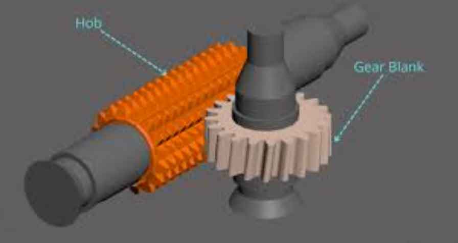
An Archimedes worm hob (Fig. 8) generates pinions via tangential shifting to prevent undercutting during modified gear hobbing. The right-side helical surface equation is:
$$\mathbf{R}_h = \begin{bmatrix}
u_h \cos\alpha_h \cos\theta_h \\
u_h \cos\alpha_h \sin\theta_h \\
u_h \sin\alpha_h – (r \tan\alpha_h + s/2) + p\theta_h \\
1
\end{bmatrix}$$
where \(p = m_h/2\), \(s = m_h\pi/2 – 2x_h m_h\), \(m_h\) is hob module, \(x_h\) is tangential shift coefficient, \(u_h\) is point position, \(\theta_h\) is rotation angle, \(\alpha_h\) is pressure angle, and \(r\) is pitch radius. Normal vector \(\mathbf{n}_h\) is:
$$\mathbf{n}_h = \begin{bmatrix}
\cos\alpha_h (p\sin\theta_h – u_h\cos\theta_h\sin\alpha_h) \\
\cos\alpha_h (u_h\sin\alpha_h\sin\theta_h + p\cos\theta_h) \\
u_h\cos^2\alpha_h \\
0
\end{bmatrix}$$
Standard cylindrical gear gear hobbing uses coordinate transformation \(\mathbf{M}_{ch}\) and meshing equations:
$$\mathbf{R}_c(\phi_h, L_s, \theta_h, u_h) = \mathbf{M}_{ch}(\phi_h, L_s)\mathbf{R}_h(\theta_h, u_h)$$
$$\mathbf{n}_c(\phi_h, L_s, \theta_h, u_h) = \mathbf{M}_{ch}(\phi_h, L_s)\mathbf{n}_h(\theta_h, u_h)$$
$$f_2 = \mathbf{n}_c \cdot \frac{\partial\mathbf{R}_c}{\partial\phi_h} = 0, \quad f_3 = \mathbf{n}_c \cdot \frac{\partial\mathbf{R}_c}{\partial L_s} = 0$$
Conjugate Pinion Gear Hobbing with CNC Motion Modifications
Conjugate pinion gear hobbing incorporates radial hob displacement \(\Delta L\) and workpiece rotation \(\Delta\phi\) (Fig. 10) to align cutting edges with the complex surface. These motions are expressed as 6th-order Taylor polynomials:
$$\Delta\phi = \sum_{n=0}^{6} a_n \phi_h^n, \quad \Delta L = \sum_{n=0}^{6} b_n \phi_h^n$$
Machined tooth surfaces become:
$$\mathbf{R}_{c1}(\phi_h, L_s, \theta_h, u_h) = \mathbf{M}_{1h}(\phi_h, L_s)\mathbf{R}_h(\theta_h, u_h)$$
$$\mathbf{n}_{c1}(\phi_h, L_s, \theta_h, u_h) = \mathbf{M}_{1h}(\phi_h, L_s)\mathbf{n}_h(\theta_h, u_h)$$
A sensitivity matrix equation minimizes deviation \(\delta_{c1}\) between CNC-machined and theoretical surfaces:
$$\mathbf{\delta}_{C1,q\times1} = \mathbf{J}_{q\times p} \Delta\mathbf{c}_{p\times1}$$
where \(\mathbf{J}\) is the sensitivity matrix computed via singular value decomposition (SVD):
$$\mathbf{J} = \mathbf{\Gamma \Omega \Lambda}^T$$
Coefficients \(\mathbf{c} = [a_n, b_n]\) are optimized iteratively until \(||\mathbf{H}|| \leq 10^{-3}\) where \(\mathbf{H} = \delta_{c1} – \mathbf{n}_c[\mathbf{R}_{c1}(\mathbf{c} + \Delta\mathbf{c}) – \mathbf{R}_c]\).
Performance Validation and Case Study
Finite element analysis compares ruled surface gear pairs (\(N_2\)=90, \(N_1\)=30, \(m\)=3mm, \(\alpha\)=25°) with traditional pairs. Stress distributions and transmission errors align closely (Fig. 12-14):
| Parameter | Max Difference |
|---|---|
| Face Gear Contact Stress | 0.67% |
| Pinion Contact Stress | 1.47% |
| Face Gear Bending Stress | 1.29% |
| Pinion Bending Stress | 1.06% |
| Transmission Error | <0.0003° |
Numerical validation (\(N_1\)=30, \(N_2\)=90, \(m\)=3mm) confirms gear hobbing accuracy:
- Max deviation between conjugate and cylindrical pinion: 14.02 μm
- Max CNC machining error: 0.65 μm
Table 2 lists optimized coefficients for \(\Delta\phi\) and \(\Delta L\):
| Coefficient | \(a_n \times 10^{-3}\) | \(b_n \times 10^{-3}\) |
|---|---|---|
| \(n=0\) | 0.0975 | 0.1066 |
| \(n=1\) | 0.0899 | 0.8267 |
| \(n=2\) | 0.0518 | 4.4619 |
| \(n=3\) | 0.1091 | -1.0736 |
| \(n=4\) | 0.0942 | 0.3606 |
| \(n=5\) | 0.0976 | 0.0342 |
| \(n=6\) | 0.0968 | 0.1098 |
VERICUT simulations (Fig. 18) demonstrate gear hobbing feasibility with maximum errors of 5.31 μm, meeting ISO Grade 5 accuracy for cylindrical gears.
Conclusion
This research establishes a comprehensive methodology for manufacturing conjugate pinions for ruled surface face gears using modified gear hobbing. By introducing radial hob displacement and workpiece rotation through optimized polynomial motions, CNC gear hobbing achieves sub-micron accuracy in conjugate pinion generation. The ruled surface gear pairs exhibit near-identical load performance to traditional pairs while enabling efficient line-contact machining. This approach eliminates transmission ratio constraints and enhances production scalability for face gear applications in compact drive systems. Future work will explore real-time compensation strategies for industrial gear hobbing machines and dynamic behavior under high-speed operations.