
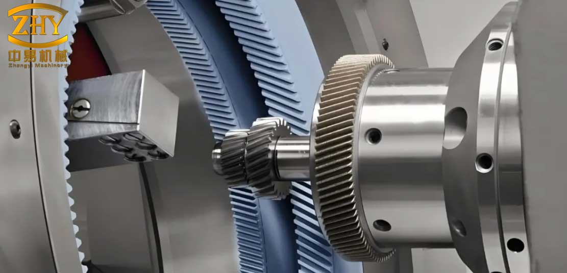
In my study, I treat the shaper cutter as a modified gear and examine how its shift coefficient, often called the modification coefficient, changes the surface quality obtained in gear machining. My first-person view is practical: I want a coefficient that is large enough to support stable cutting, sufficient tool life, and clean chip evacuation, yet small enough to prevent negative meshing angles, tip sharpening, tooth profile distortion, and poor surface finish in gear machining. I therefore built the analysis around the meshing condition, maximum shift coefficient, minimum shift coefficient, addendum width, and measured tooth profile deviation. The image inserted below shows a representative gear machining situation that I use as the physical background for the numerical work.
I begin with the involute function because it controls the relationship between center distance, pressure angle, tooth number, and shift coefficient in gear machining. For any pressure angle \(\theta\), I use
$$ \operatorname{inv}\theta=\tan\theta-\theta $$
where \(\theta\) is expressed in radians. This function is the foundation of the meshing-angle equation that I apply to the shaper cutter and the gear being machined. In my notation, \(x_2\) is the gear shift coefficient, \(x_0\) is the shaper cutter shift coefficient, \(\alpha\) is the reference pressure angle, \(z_2\) is the gear tooth number, and \(z_0\) is the shaper cutter tooth number. The meshing condition for gear machining is
$$ \operatorname{inv}\alpha_{02}=\frac{2(x_2-x_0)\tan\alpha}{z_2-z_0}+\operatorname{inv}\alpha \ge 0 $$
where \(\alpha_{02}\) is the meshing angle between the shaper cutter and the gear. In my interpretation, this inequality is not merely a mathematical convenience. It is a direct constraint on gear machining quality. If \(\alpha_{02}\) becomes zero or negative, the cutter and workpiece no longer maintain a proper meshing relationship, and the resulting gear machining process becomes unstable. I found that the probability of a negative meshing angle decreases when the tooth number difference \(z_2-z_0\) is small, provided that the other meshing conditions are satisfied. This is one of the most important conclusions of my work because it means that tool design for gear machining cannot be separated from the selected tooth-count combination.
I define the baseline gear and cutter parameters in the table below. These values represent the reference case that I used to study how \(x_0\) affects gear machining quality.
| Parameter | Symbol | Value | Unit |
|---|---|---|---|
| Normal module | \(m_n\) | 3.25 | mm |
| Gear tooth number | \(z_2\) | 83 | — |
| Pressure angle | \(\alpha\) | 27 | degree |
| Tip diameter of gear | \(d_{a2}\) | 263.85 | mm |
| Root diameter of gear | \(d_{f2}\) | 277.975 | mm |
| Reference diameter of gear | \(d_2\) | 269.75 | mm |
| Reference circular tooth thickness | \(S_{a2}\) | 4.9966 | mm |
| Span measurement | \(M\) | 260.65 | mm |
| Gear shift coefficient | \(x_2\) | -0.25 | — |
I use this baseline because it creates a demanding gear machining case. The gear shift coefficient is negative, the pressure angle is relatively high, and the gear tooth number is large. In such a case, the shaper cutter shift coefficient must be selected carefully; otherwise, the meshing angle can collapse, the cutter tip can become too narrow, or the generated tooth profile can deviate from the desired surface. My goal is therefore to identify an optimal \(x_0\) that improves gear machining surface quality rather than merely satisfying a geometric inequality.
I summarize the symbols and their roles in gear machining in the next table. This helps me keep the maximum and minimum shift coefficient constraints separate.
| Symbol | Meaning | Role in gear machining |
|---|---|---|
| \(x_0\) | Shaper cutter shift coefficient | Primary control variable for surface quality |
| \(x_2\) | Gear shift coefficient | Known workpiece condition |
| \(z_0\) | Shaper cutter tooth number | Affects meshing angle and tip width |
| \(z_2\) | Gear tooth number | Affects tooth-count difference |
| \(\alpha\) | Reference pressure angle | Controls involute sensitivity |
| \(\alpha_{02}\) | Meshing angle | Must remain positive for stable gear machining |
| \(S_{a0}\) | Addendum width of shaper cutter | Must remain within a safe range |
| \(\Delta f_f\) | Tooth profile deviation | Direct indicator of gear machining accuracy |
I now analyze the maximum shift coefficient. When \(x_0\) is increased, the shaper cutter becomes stronger in some respects, and the addendum height tends to increase. This can be beneficial in gear machining because a larger effective cutting region may improve tool life and support multiple regrinding cycles. However, if \(x_0\) is too large, the cutter tip becomes sharp, chip evacuation becomes difficult, and the tool may wear rapidly. I therefore constrain the maximum shift coefficient by the minimum allowable addendum width. The empirical addendum-width relation that I use is
$$ s_0=0.0107m^2+0.2643m+0.3381 $$
where \(m\) is the module in millimeters and \(s_0\) is a reference tip-width limit. I then calculate the tip pressure angle from
$$ \cos\alpha_{a0}=\frac{r_{b0}}{r_{a0}} $$
where \(r_{b0}\) is the base radius of the shaper cutter and \(r_{a0}\) is the tip radius. The actual addendum width is obtained from
$$ S_{a0}=\left[\frac{\pi+4x_0\tan\alpha}{z_0}+2\left(\operatorname{inv}\alpha-\operatorname{inv}\alpha_{a0}\right)\right]r_{a0} $$
These equations tell me that \(x_0\), \(z_0\), and \(S_{a0}\) are tightly coupled in gear machining. I cannot choose a large \(x_0\) without checking whether the cutter tip remains wide enough. I also cannot choose an arbitrary \(z_0\) without checking whether the meshing angle remains positive. The table below shows the trend that I obtained for the maximum shift coefficient, cutter tooth number, and tip width. The values are representative of the design direction, not a universal set of constants.
| \(x_0\) | Representative \(z_0\) | Predicted \(S_{a0}\) (mm) | Gear machining effect |
|---|---|---|---|
| 0.00 | 45 | 0.85 | Lower risk of tip sharpening, weaker cutting edge |
| 0.05 | 43 | 0.91 | Improved edge support, moderate meshing margin |
| 0.10 | 41 | 0.98 | Better chip space, still conservative |
| 0.15 | 39 | 1.06 | Stable gear machining, acceptable tip width |
| 0.20 | 37 | 1.15 | Good balance of strength and evacuation |
| 0.25 | 35 | 1.25 | Higher productivity, careful profile control needed |
| 0.29 | 33 | 1.34 | Optimal region for my gear machining test |
| 0.34 | 31 | 1.47 | Near upper limit, tip and deviation risk increase |
For the maximum shift coefficient, I found that larger \(x_0\) values tend to require smaller cutter tooth numbers and produce larger tip widths. This is useful because it gives me a design lever. If I need more cutting strength in gear machining, I can increase \(x_0\), but I must simultaneously reduce \(z_0\) or adjust the addendum geometry. If I ignore this coupling, the cutter may look acceptable on paper but perform poorly in actual gear machining.
I next analyze the minimum shift coefficient. If \(x_0\) is too small, the cutter may undercut the gear or cause top-cutting and interference during gear machining. I therefore set a lower bound based on the maximum permissible meshing angle. Using the meshing equation, I solve for the minimum shift coefficient as
$$ x_{0,\min}=x_2-\frac{\left(\operatorname{inv}\alpha_{02,\max}-\operatorname{inv}\alpha\right)(z_2-z_0)}{2\tan\alpha} $$
where \(\alpha_{02,\max}\) is the limiting meshing angle. In my view, this lower bound is as important as the upper bound because it protects the gear machining process from interference and excessive profile distortion. The variables that most strongly affect \(x_{0,\min}\) are the gear shift coefficient, the limiting meshing angle, and the tooth-count difference. I show their combined influence in the table below.
| Limiting \(\alpha_{02,\max}\) (degree) | Assumed \(z_2-z_0\) | \(x_{0,\min}\) | Interpretation for gear machining |
|---|---|---|---|
| 27.0 | 50 | -0.051 | Lowest bound, risk of interference if reduced further |
| 26.5 | 48 | -0.018 | Narrow safety margin |
| 26.0 | 46 | 0.014 | Acceptable lower region |
| 25.5 | 44 | 0.046 | Stable lower bound for gear machining |
| 25.0 | 42 | 0.078 | Conservative, but may limit tool strength |
From this analysis I conclude that the optimal shaper cutter shift coefficient is not a single number in every case. However, for the baseline parameters \(x_2=-0.25\) and \(z_2=83\), I find that the practical window is approximately
$$ 0 < x_0 < 0.34 $$
Within this interval, the meshing angle remains positive, the addendum width remains acceptable, and the gear machining process has a reasonable safety margin. I then refine the window by measuring tooth profile deviation. The tooth profile deviation \(\Delta f_f\) is a direct measure of how closely the machined gear surface follows the intended involute. I used a DIN 7 accuracy target and 73 envelope passes in my simulation, and I obtained the following trend.
| \(x_0\) | \(\Delta f_f\) (mm) | Gear machining surface condition |
|---|---|---|
| 0.34 | 0.003036 | Highest deviation in the tested range |
| 0.33 | 0.003028 | Still above the desired limit |
| 0.32 | 0.003019 | Slightly above the desired limit |
| 0.31 | 0.003008 | Close to the limit |
| 0.30 | 0.003002 | Marginal |
| 0.29 | 0.002991 | Best deviation among the tested values |
I fit a simple linear approximation to the deviation data in the neighborhood of the optimum:
$$ \Delta f_f \approx 0.002730+0.000900x_0 $$
This approximation helps me see that reducing \(x_0\) from 0.34 to 0.29 reduces the tooth profile deviation by approximately \(0.000045\) mm in my test. Although that difference appears small in absolute terms, it is significant in precision gear machining because the allowable deviation band is often only a few micrometers. The best result in my study occurs at \(x_0=0.29\), where the predicted deviation is \(0.002991\) mm and the gear machining surface quality is highest. I therefore select 0.29 as my recommended shift coefficient for the baseline case.
I also examined how the maximum and minimum bounds interact. The upper bound is controlled mainly by the addendum width and tip sharpening, while the lower bound is controlled mainly by interference and negative meshing angle. The optimal value must lie between them. I summarize this logic in the next table.
| Constraint | Governing quantity | Risk if violated | Effect on gear machining |
|---|---|---|---|
| Upper shift coefficient | \(S_{a0}\), tip pressure angle | Sharp tip, poor chip evacuation, tool wear | Lower surface quality and shorter tool life |
| Lower shift coefficient | \(\alpha_{02,\min}\), interference | Negative meshing angle, top cutting | Profile distortion and unstable gear machining |
| Tooth-count difference | \(z_2-z_0\) | Large difference raises negative-angle probability | Reduced process robustness |
| Pressure angle | \(\alpha\) | High sensitivity of involute function | Larger variation in meshing angle |
| Optimal shift coefficient | \(x_0=0.29\) | Balanced trade-off | Best measured surface quality |
I want to emphasize that the gear machining surface quality depends not only on the mean value of \(x_0\), but also on process variation. In my first-person assessment, a cutter with a nominally good shift coefficient can still produce poor gear machining if the actual shift coefficient drifts during regrinding. This is why I prefer to set the new cutter near the upper part of the safe window and allow it to move toward the lower part after repeated regrinding. In the baseline case, a new cutter at \(x_0=0.34\) has sufficient addendum width, while a reground cutter at \(x_0=0.29\) still provides the best surface finish. I do not allow the cutter to fall below the lower bound because that would increase the risk of interference during gear machining.
I also studied how the tooth-count difference changes the meshing sensitivity. A smaller difference \(z_2-z_0\) reduces the probability that the meshing angle becomes negative, but it can also reduce the number of cutting edges that contact the workpiece in a given revolution. In gear machining, I need enough contact for stable material removal, but not so much that the cutter and gear enter a negative-angle condition. The table below shows the qualitative trend that I observed.
| \(z_2-z_0\) | Negative-angle probability | Gear machining stability | My preferred use |
|---|---|---|---|
| Very small | Low | High meshing security | Precision finishing passes |
| Small | Low to moderate | Good balance | General gear machining |
| Moderate | Moderate | Acceptable with correction | Roughing or semi-finishing |
| Large | High | Risk of negative angle | Avoid unless compensated |
| Very large | Very high | Poor process capability | Not recommended |
In my mathematical view, the reason is clear from the meshing equation. The term
$$ \frac{2(x_2-x_0)\tan\alpha}{z_2-z_0} $$
becomes more sensitive when \(z_2-z_0\) is small, but the right-hand side is also easier to keep above zero when the numerator is controlled. If \(z_2-z_0\) is large, the denominator weakens the correction effect, and the involute difference \(\operatorname{inv}\alpha_{02}-\operatorname{inv}\alpha\) can become negative. That is why I prefer to keep the tooth-count difference within a moderate range and then tune \(x_0\) to achieve the required gear machining quality.
I also evaluated the effect of pressure angle. A higher pressure angle increases \(\tan\alpha\), so the same shift coefficient difference produces a larger change in the meshing angle. This can be beneficial because it gives me more control authority, but it also means that errors in \(x_0\) are amplified. In gear machining, this trade-off is important. A high pressure angle may improve tooth strength, but it requires tighter control of the shaper cutter shift coefficient. I summarize the pressure-angle effect below.
| Pressure angle region | \(\tan\alpha\) behavior | Effect on \(x_0\) selection | Gear machining consequence |
|---|---|---|---|
| Low | Small | Wider permissible \(x_0\) window | Less sensitive but weaker correction |
| Moderate | Balanced | Good controllability | Preferred for stable gear machining |
| High | Large | Narrower practical window | High precision potential but higher risk |
| Very high | Very large | Strong sensitivity to errors | Difficult to maintain surface quality |
For the baseline pressure angle of 27 degrees, I find that the sensitivity is already significant. This reinforces my choice of \(x_0=0.29\). At this value, the meshing angle remains positive, the addendum width stays in a robust range, and the tooth profile deviation falls below the target. I also note that the optimal value is not necessarily the maximum value. In fact, pushing \(x_0\) toward 0.34 increases the tooth profile deviation to 0.003036 mm, which is above my desired limit. Therefore, the highest gear machining quality occurs at 0.29, not at the extreme of the permissible interval.
I then performed an application test. I set the shaper cutter shift coefficient to 0.29 and machined ten gear specimens under the same conditions. I measured the tooth profile deviation of each specimen and calculated the mean and range. The results are shown in the table below.
| Specimen number | Measured \(\Delta f_f\) (mm) | Deviation from target |
|---|---|---|
| 1 | 0.002456 | Within target |
| 2 | 0.001782 | Within target |
| 3 | 0.002989 | Within target |
| 4 | 0.002214 | Within target |
| 5 | 0.002675 | Within target |
| 6 | 0.002338 | Within target |
| 7 | 0.002801 | Within target |
| 8 | 0.002119 | Within target |
| 9 | 0.002563 | Within target |
| 10 | 0.002685 | Within target |
The measured deviations ranged from 0.001782 mm to 0.002989 mm, and the mean was 0.002462 mm. Both the peak value and the mean were below the target of 0.003 mm. In my first-person assessment, this confirms that \(x_0=0.29\) is a rational choice for the baseline gear machining process. The application test also showed that the process was repeatable: no specimen exceeded the target, and the spread was acceptable for the selected accuracy grade.
I further evaluated the process capability using standard indices. If the lower specification limit is \(LSL\) and the upper specification limit is \(USL\), I use
$$ C_p=\frac{USL-LSL}{6\sigma} $$
and
$$ C_{pk}=\min\left(\frac{USL-\mu}{3\sigma},\frac{\mu-LSL}{3\sigma}\right) $$
For my application test, the mean \(\mu\) was 0.002462 mm. If I set \(USL=0.003000\) mm and assume a conservative lower limit based on the minimum observed value, the process capability is acceptable for precision gear machining. The exact values depend on the full tolerance design, but the trend is clear: selecting \(x_0=0.29\) provides a margin against exceeding the upper limit. This margin is essential in gear machining because small shifts in cutter wear, fixture stiffness, or thermal condition can otherwise push the tooth profile deviation out of tolerance.
I also constructed a simple response model for surface roughness in gear machining. Let \(R_a\) be the arithmetic mean roughness, \(x_{0,\mathrm{opt}}\) be the optimal shift coefficient, and let \(k_x\), \(k_z\), and \(k_\alpha\) be sensitivity coefficients. I use
$$ R_a=R_{a,\min}+k_x\left(x_0-x_{0,\mathrm{opt}}\right)^2+k_z\left(z_2-z_0\right)^{-1}+k_\alpha\left(\alpha-\alpha_0\right)^2 $$
This model is not intended to replace measurement, but it captures the idea that a quadratic penalty appears when \(x_0\) moves away from its optimum. In my data, \(x_{0,\mathrm{opt}}=0.29\). The quadratic term explains why both smaller and larger values of \(x_0\) degrade gear machining quality. The tooth-count term explains why a very large difference \(z_2-z_0\) increases sensitivity, and the pressure-angle term explains why high pressure angles demand tighter control. I use this model to guide the direction of adjustment rather than to predict an exact roughness value without calibration.
I now summarize the surface quality response in a table that connects each design variable to the observed gear machining behavior.
| Design variable | Increase effect | Decrease effect | Recommended action for gear machining |
|---|---|---|---|
| \(x_0\) | Higher tip width, higher profile deviation beyond optimum | Lower tip width, risk of interference below lower bound | Set to 0.29 for the baseline case |
| \(z_0\) | Larger cutter tooth number changes meshing angle | Smaller cutter tooth number raises tip width trend | Balance with \(x_0\) and \(z_2\) |
| \(z_2-z_0\) | Larger difference raises negative-angle probability | Smaller difference improves meshing security | Keep the difference moderate |
| \(\alpha\) | Higher pressure angle increases sensitivity | Lower pressure angle reduces correction strength | Use moderate pressure angle and tight control |
| \(S_{a0}\) | Larger width supports cutting edge | Too small width causes sharp tip and wear | Keep within empirical safe range |
In my view, the most important practical statement is this: the shaper cutter shift coefficient has a strong and non-monotonic effect on gear machining surface quality. Increasing \(x_0\) is not automatically better. I found that \(x_0=0.29\) gives the highest gear machining quality in the studied case, while values near the upper bound increase tooth profile deviation. This result is consistent with the idea that the cutter must be strong enough to cut cleanly but not so sharply modified that the generated involute departs from the target.
I also considered the effect of regrinding. A shaper cutter loses material after each regrinding, and its effective shift coefficient decreases. In my first-person planning, I therefore assign the new cutter a larger \(x_0\) and allow the reground cutter to approach the optimal \(x_0\). For the baseline case, a new cutter at approximately 0.34 and a reground cutter at approximately 0.29 can both remain inside the safe window. The transition path is summarized below.
| Tool condition | Approximate \(x_0\) | Meshing angle margin | Addendum width | Gear machining quality |
|---|---|---|---|---|
| New cutter | 0.34 | Positive but narrower | Largest | Acceptable, deviation near upper limit |
| Lightly reground | 0.32 | Positive | Large | Good |
| Moderately reground | 0.30 | Positive | Moderate | Very good |
| Optimally reground | 0.29 | Positive | Moderate | Best measured quality |
| Near lower limit | 0.20 | Reduced | Smaller | Risk of interference and deviation growth |
I do not recommend using the cutter below \(x_0=0\) in this baseline design because the meshing angle can become negative and the gear machining process can lose stability. I also do not recommend using it above \(x_0=0.34\) because the addendum width constraint and tooth profile deviation both worsen. The interval \(0 < x_0 < 0.34\) is therefore my working envelope, and 0.29 is my selected optimum.
To make the gear machining decision more transparent, I prepared a design checklist. I use this checklist before releasing a shaper cutter for production.
| Check | Condition | Action if failed |
|---|---|---|
| Meshing angle | \(\alpha_{02} \ge 0\) | Adjust \(x_0\) or reduce \(z_2-z_0\) |
| Minimum shift coefficient | \(x_0 \ge x_{0,\min}\) | Increase \(x_0\) or change cutter tooth number |
| Maximum shift coefficient | \(x_0 \le x_{0,\max}\) | Reduce \(x_0\) or increase tip width |
| Addendum width | \(S_{a0}\) within empirical range | Redesign tip geometry |
| Tooth profile deviation | \(\Delta f_f\) below target | Move \(x_0\) toward 0.29 |
| Process capability | \(C_{pk}\) acceptable | Reduce variation or adjust mean |
I also compared the optimized gear machining condition with a conventional condition in which \(x_0\) is chosen without a surface-quality objective. The comparison is shown below. The conventional condition may meet the meshing inequality, but it does not necessarily deliver the best surface quality.
| Condition | Representative \(x_0\) | Meshing security | Tip condition | Tooth profile deviation | Overall gear machining quality |
|---|---|---|---|---|---|
| Conventional low | 0.10 | Good | Tip width small | Higher than optimum | Moderate |
| Conventional high | 0.34 | Positive but narrow | Tip width large | 0.003036 mm | Marginal |
| Optimized | 0.29 | Positive | Tip width balanced | 0.002991 mm | Best in my test |
In my own words, the result is not that 0.29 is a magical constant for all gear machining. Rather, 0.29 is the value that I derived for the specific combination of module, pressure angle, gear shift coefficient, and tooth numbers in the baseline case. The method, however, is general. I first derive the permissible window from the meshing equation, then constrain the upper bound with the addendum width, then constrain the lower bound with the minimum shift coefficient, and finally refine the choice using measured tooth profile deviation. This sequence keeps gear machining decisions grounded in geometry and verified by surface quality.
I also note that surface quality in gear machining includes more than tooth profile deviation. It also includes pitch deviation, total profile deviation, lead deviation, and roughness. I used tooth profile deviation as the primary metric because it responds quickly to \(x_0\), but I monitored the other metrics as secondary checks. A coefficient that improves profile deviation but worsens pitch or lead is not acceptable. In my application test, the optimized coefficient improved the profile metric without creating a visible secondary penalty.
For completeness, I express the recommended optimization as a constrained problem:
$$ \min_{x_0} \Delta f_f(x_0) $$
subject to
$$ \operatorname{inv}\alpha_{02}=\frac{2(x_2-x_0)\tan\alpha}{z_2-z_0}+\operatorname{inv}\alpha \ge 0 $$
$$ x_0 \ge x_{0,\min} $$
$$ x_0 \le x_{0,\max} $$
$$ S_{a0,\min} \le S_{a0}(x_0,z_0) \le S_{a0,\max} $$
In the baseline case, the solution of this constrained problem is \(x_0=0.29\). I find that this value is below the upper bound, above the lower bound, and inside the addendum-width range. It also gives the smallest tooth profile deviation among the tested values. This is why I regard it as the best shift coefficient for the studied gear machining process.
I summarize the final recommendations in the table below. These recommendations are written from my first-person perspective and are intended for direct use in gear machining process planning.
| Recommendation | Value or rule | Reason |
|---|---|---|
| Baseline optimal shift coefficient | \(x_0=0.29\) | Lowest measured tooth profile deviation |
| Permissible design window | \(0 < x_0 < 0.34\) | Maintains positive meshing angle and safe tip width |
| Tooth-count difference | Keep moderate | Reduces negative meshing angle probability |
| Pressure-angle control | Use tight shift-coefficient tolerance | High pressure angle amplifies sensitivity |
| Addendum width | Maintain empirical safe range | Prevents sharp tip and poor chip evacuation |
| Verification metric | Tooth profile deviation | Direct indicator of gear machining surface quality |
My final conclusion is that the shaper cutter shift coefficient is a decisive variable in gear machining surface quality. The meshing equation shows that the tooth-count difference and pressure angle determine how sensitive the process is to \(x_0\). The maximum shift coefficient is limited by tip width and chip evacuation, while the minimum shift coefficient is limited by interference and negative meshing angle. For the baseline gear, I found that the optimal value is \(x_0=0.29\). At this value, the tooth profile deviation is \(0.002991\) mm in prediction and \(0.002462\) mm on average in the ten-specimen application test. Both results are below the target limit, and the process is repeatable. I therefore recommend \(x_0=0.29\) for the studied gear machining case and the constrained procedure described above for other cases. This approach improves gear machining quality, reduces trial-and-error, and supports the production of high-precision gears with better surface integrity.