
As the project requires to find a practical production way suitable for the factory, a high-speed, single action and single crank mechanical press is selected in this study. Because the gear forging is heated, the thermal expansion and cold shrinkage of the material and the deformation of the die must be considered. Therefore, the finite element method is used for accurate calculation. In addition, the gear forging process is simulated by finite element to ensure the accuracy of gear forging. The experiment shows that the error of forging steel gear between 850 ℃ and 950 ℃ can be controlled in the range of 0 ∙ 05mm.
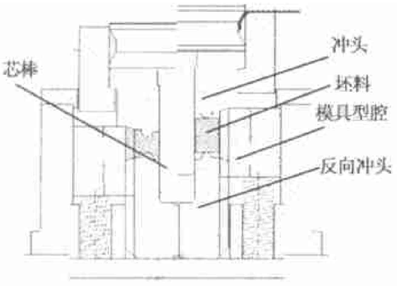
Hollow cylindrical blanks are often used for forging hollow axisymmetric parts or gears. Figure 1 shows the design of a closed die forging for cylindrical spur gears. In the figure, the right side shows the situation before gear forging and the left side shows the situation after gear forging. The die consists of an upper die (punch), a lower die (reverse punch), a mandrel and a contour cavity (as shown in the figure). The die cavity is supported by a spring. During the gear forging process, the punch moves downward with the sliding block of the press and drives the die cavity to move downward. Because the punch only needs to seal the upper surface of the cavity without pressing into the cavity, the punch can be made into a simple shape. In this design, the punch is a stepped cylindrical shape. The reverse punch keeps stationary during the gear forging process and pushes the gear out of the cavity after the gear forging. The mandrel is connected with the punch here to help the positioning of the blank. Because the cavity moves with the forging in the gear forging process, the friction between the cavity and the gear forging will help the metal flow, and the required load is lower than that when the cavity is fixed.
In the process of gear forging, the basic function of the die is to make the parts form correctly. The die design of this kind of gear forging is widely and deeply discussed. Due to the limitations of forging types and equipment, there are many combinations of dies. The influence of die structure, die design and equipment on the accuracy of gear forging in general precision forging is widely studied.
The shape of gear forging is not only affected by high temperature thermal expansion, but also related to the elastic deformation of die, which is related to load and radial pressure. In gear forging, the corners of gear teeth are finally formed. It is in this final filling stage that the load rises sharply. The example shows that the last 0 ∙ 3mm stroke of the punch (1 ∙ 2% total deformation) will lead to a 50% increase in load. The load can be reduced by considering the die design. For example, the introduction of chamfer can make the metal easy to flow into the upper and lower corners of the gear teeth; The resulting end allowance can be easily removed in the subsequent cutting process. In this way, the distortion of the die is reduced, the service life is prolonged, and the accuracy of the gear forging is improved. For the example of cylindrical spur gear involved in this paper, several possible die design schemes are analyzed in detail: such as fixing the die cavity, chamfering the punch and punch, and the flow of metal, the formation of gear teeth and the variation of gear forging load are analyzed by finite element method. The effects of friction on deformation and load under various conditions are also discussed.

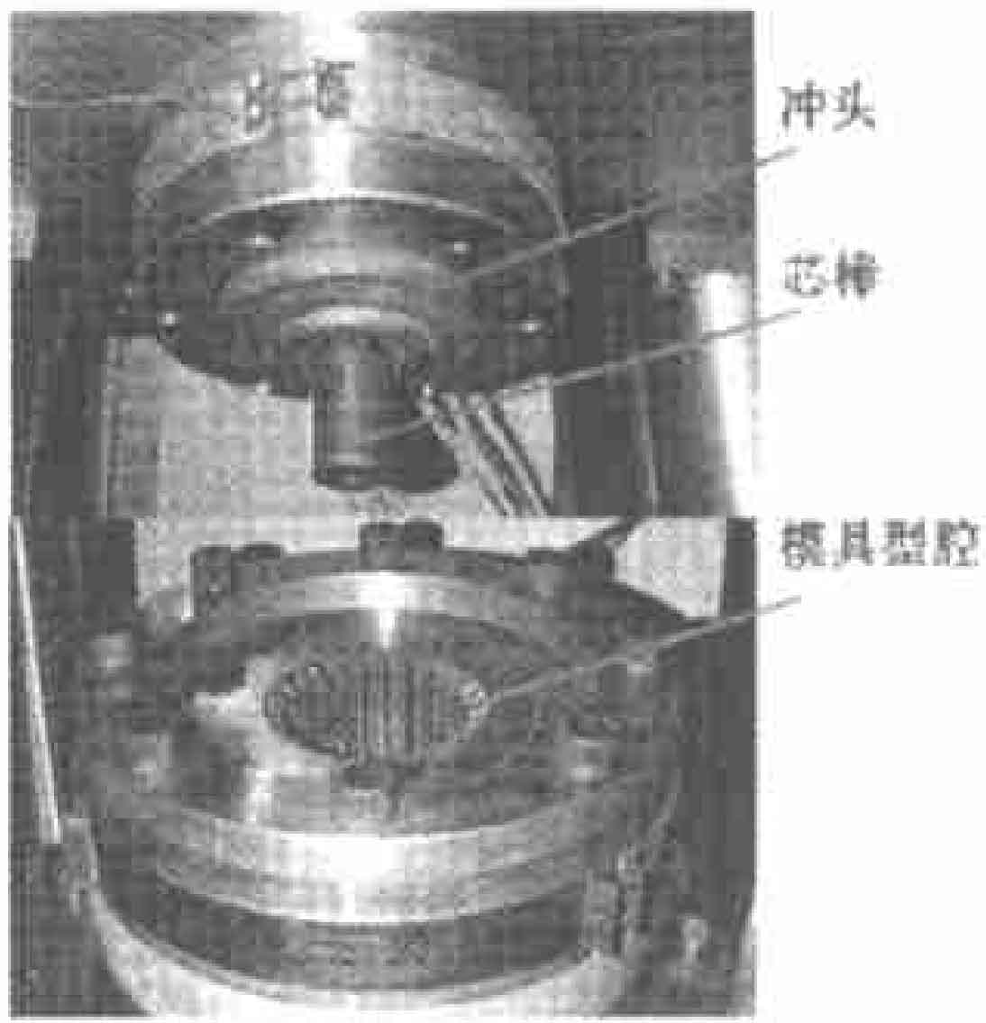
Figure 2 shows a die designed and manufactured according to figure 1, which is assembled on a 1200t mechanical press in the school of mechanical engineering of Birmingham University. The relative positioning of the upper and lower dies is realized by two sleeves. Through practice, it is proved that high efficiency gear forging is feasible. The first mock exam is done by using the same mould frame, and the forging of spur gear, helical gear and compound gear is completed.
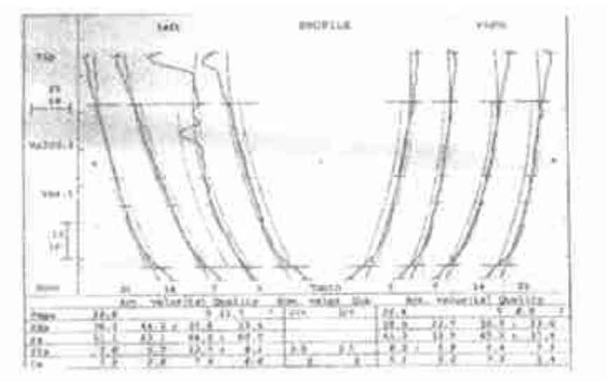
Figure 3 shows the warm forged cylindrical spur gear, helical gear and synchronous gear on this equipment. During warm forging of gear, the blank is heated to 900 ℃ and the die is heated to 200 ℃, and water-based graphite is used as lubricant. Fig. 4 shows the measurement results of the cylindrical spur gear after warm forging of the gear. It can be seen that the tooth shape of the forged gear is consistent, and the contour has an allowance of 0 ∙ 08mm ~ 0 ∙ 1mm for correction in the subsequent cold treatment process. Since the temperature is controlled at about 900 ℃, the surface quality of gear teeth is also high, RA is 3 μ M or so.